Ti/TiN/MaN composite coating on surface of cutter and preparation method of Ti/TiN/MaN composite coating
A composite coating and cutting tool technology, applied in the direction of coating, cutting tools for lathes, metal material coating process, etc., can solve the problems of poor comprehensive performance and stability, achieve good consistency and uniformity, and ensure stability , the effect of high purity
- Summary
- Abstract
- Description
- Claims
- Application Information
AI Technical Summary
Problems solved by technology
Method used
Image
Examples
Embodiment 1
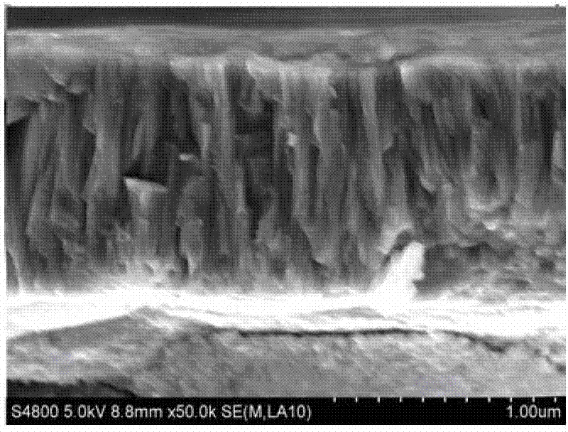
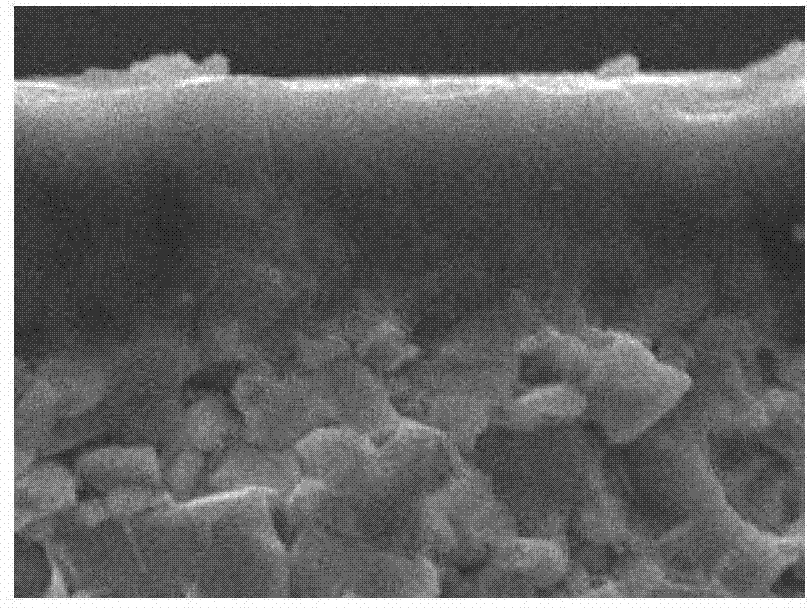
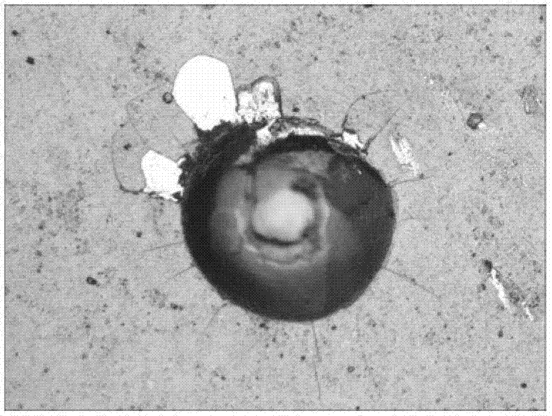
[0036] The high-speed steel hob is sandblasted and ultrasonically cleaned by conventional methods, and then put into the coating machine, and then the coating chamber is vacuumed to 5.0×10 -3 Pa, argon gas is introduced to make the total pressure in the coating machine 3.5×10 -1 Pa, and control the heating power 9KW to heat the tool to be plated for 120min; at a pressure of 2.0×10 -1 Under the protection of Pa argon gas, the DC bias voltage of the control tool is -200V, the pulse bias voltage is -800V, and the tool to be plated is cleaned with a plasma power of 6KW for 30min; at a pressure of 1.5×10 -1Under the protection of Pa argon gas, heat the Ti evaporation source with a plasma enhanced source with a power of 10KW, and plate at a DC bias of -200V and a pulse bias of -600V for 10min; feed 150 sccm of nitrogen, and continue to work together with the Ti evaporation source at a power of 10KW , plating at DC bias -200V for 10min; use intermediate frequency reactive magnetron ...
Embodiment 2
[0039] Put the high-speed steel drill bit into the coating machine after sandblasting and ultrasonic cleaning by conventional methods, and then vacuumize the coating chamber to 5.0×10 -3 Pa, argon gas is introduced to make the total pressure in the coating machine 2.5×10 -1 Pa, and control the heating power 7KW to heat the tool to be plated for 60min; at a pressure of 2.5×10 -1 Under the protection of Pa argon gas, the DC bias voltage of the control tool is -100V, the pulse bias voltage is -500V, and the tool to be plated is cleaned with a plasma power of 4KW for 15min; at a pressure of 1.2×10 -1 Under the protection of Pa argon gas, heat the Ti evaporation source with a plasma enhanced source with a power of 7.5KW, and plate at a DC bias of -100V and a pulse bias of -400V for 5min; feed 110sccm of nitrogen, and continue to work together with the Ti evaporation source 7.5KW, DC bias -130V for 5 minutes; use intermediate frequency reactive magnetron sputtering to sputter compo...
Embodiment 3
[0042] Carbide milling cutters are subjected to sand blasting and ultrasonic cleaning by conventional methods, and then put into the coating machine, and then the coating chamber is vacuumed to 5.0×10 -3 Pa, argon gas is introduced to make the total pressure in the coating machine 4.0×10 -1 Pa, and control the heating power 9KW to heat the tool to be plated for 150min; at a pressure of 1.8×10 -1 Under the protection of Pa argon gas, the DC bias voltage of the control tool is -200V, the pulse bias voltage is -600V, and the tool to be plated is cleaned with a plasma power of 6KW for 30min; at a pressure of 8×10 -2 Under the protection of Pa argon gas, heat the Ti evaporation source with a plasma enhanced source with a power of 9KW, and plate at a DC bias of -200V and a pulse bias of -400V for 8min; feed 100 sccm of nitrogen, and continue to work together with the Ti evaporation source at a power of 9KW , plating at DC bias -150V for 10min; use intermediate frequency reactive ma...
PUM
| Property | Measurement | Unit |
|---|---|---|
| Thickness | aaaaa | aaaaa |
| Thickness | aaaaa | aaaaa |
| Thickness | aaaaa | aaaaa |
Abstract
Description
Claims
Application Information
 - R&D
- Intellectual Property
- Life Sciences
- Materials
- Tech Scout
- Unparalleled Data Quality
- Higher Quality Content
- 60% Fewer Hallucinations
Browse by: Latest US Patents, China's latest patents, Technical Efficacy Thesaurus, Application Domain, Technology Topic, Popular Technical Reports.
© 2025 PatSnap. All rights reserved.Legal|Privacy policy|Modern Slavery Act Transparency Statement|Sitemap|About US| Contact US: help@patsnap.com


