
Steel-steel double-metal rotor and manufacturing method thereof

A bimetallic and rotor technology, applied in liquid fuel engines, mechanical equipment, components of pumping devices for elastic fluids, etc., can solve the problem of low melting point of copper alloy, pull out of the copper alloy layer in the plunger hole, and bond strength low level problem

Inactive Publication Date: 2014-04-30
CENT IRON & STEEL RES INST
View PDF11 Cites 7 Cited by
  • Summary
  • Abstract
  • Description
  • Claims
  • Application Information

AI Technical Summary

Problems solved by technology

[0005] However, the existing copper-steel bimetallic rotors cannot meet the requirements of a new generation of high-speed, high-pressure, and large-flow hydraulic pumps, especially kerosene pumps. The main problems are:
[0006] ① Copper alloy anti-friction layer has limited wear resistance
Copper-steel bimetallic rotors have different thermal expansion coefficients and large differences in thermal deformation, which is prone to plunger locking, causing complete twisting or damage of chucks, sliding shoes and other parts in the pump, and paralyzing the system.
If it is necessary to ensure sufficient deformation at high temperature, the gap between the plunger hole and the plunger of the rotor at normal temperature will be too large, which will reduce the volumetric efficiency
At the same time, due to the difference in thermal deformation, the rotor is prone to cracks during heat treatment.
[0008] ③The copper alloy of the anti-friction layer is prone to fatigue wear, which causes the copper to transfer to the steel substrate, resulting in copper sticking, that is, the phenomenon of "cold welding", which affects the normal operation of the friction pair
[0009] ④Due to the low melting point of the copper alloy, the diffusion welding temperature is limited, and the strength of the copper alloy itself is low (for example, the σ of ZQSn10-2-3 b is 245MPa), therefore, the bonding strength of the copper-steel bimetallic friction pair is low, and the copper alloy layer on the end surface often falls off and the copper alloy layer in the plunger hole is pulled out.

Method used


Image

  • Steel-steel double-metal rotor and manufacturing method thereof
  • Steel-steel double-metal rotor and manufacturing method thereof
  • Steel-steel double-metal rotor and manufacturing method thereof

Examples


Embodiment

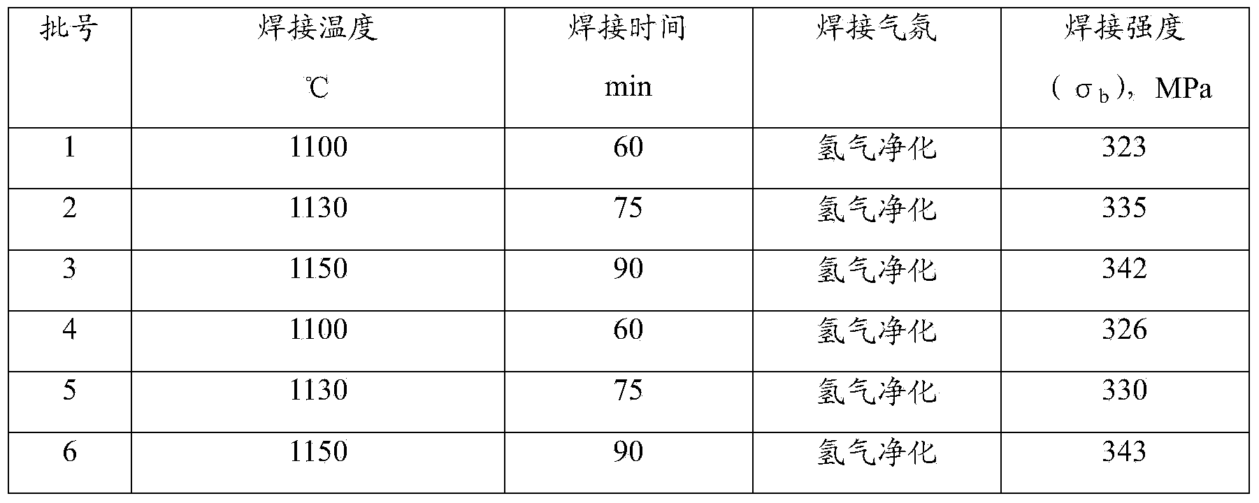
[0048] Using the bimetal manufacturing process of the present invention, 6 batches of welding samples were prepared. Table 1 shows the materials used in the preparation of welding samples, and Table 2 shows the process parameters and welding performance of the preparation of welding samples. For comparison, Table 2 lists the welding strength of Cu-steel diffusion welding bimetallic materials.

[0049] Table 1 Materials used to prepare welding samples

[0050] batch number

Anti-friction layer material

Matrix material

Welding materials

1

Self-lubricating wear-resistant steel anti-friction layer material

40CrNiMoA

Cu-10Sn-20Ni

2

Self-lubricating wear-resistant steel anti-friction layer material

40CrNiMoA

Cu-10Sn-20Ni

3

Self-lubricating wear-resistant steel anti-friction layer material

40CrNiMoA

Cu-10Sn-20Ni

4

Self-lubricating wear-resistant steel anti-friction layer material

40CrNiMoA ...


PUM


Abstract

The invention belongs to the field of metallurgical materials, and particularly relates to a steel-steel double-metal rotor and a manufacturing method thereof. A rotor substrate is made by adopting steel or nodular cast iron, a friction reducing layer is made by adopting a self-lubricating wear-resistant steel material, and a final product of the self-lubricating wear-resistant steel material is chemically composed of, by mass, 0.5-1% of C, 11-13% of Cr, 8-10% of Ni, 1.5-2.5% of Mo, 25-30% of Cu, 3-9% of MoS2, 0.5-1.5% of nano alpha-Al2O3 and the balance Fe. The rotor is manufactured by the following method including preparing the self-lubricating wear-resistant steel friction reducing layer material, namely mixing graphite powder, ferrochrome powder, ferromolybdenum powder, nickel carbonyl powder, nano alpha-Al2O3 powder and a binder with iron powder for pressing and sintering; performing copper leaching to obtain the self-lubricating wear-resistant steel friction reducing layer material; spreading the self-lubricating wear-resistant steel friction reducing layer material on a flow distributing face and a plunger hole surface of the rotor respectively, and preparing a friction reducing layer through a diffusion welding process, wherein welding temperature is 1100-1150 DEG C, and welding time is 1-2 hours.

Description

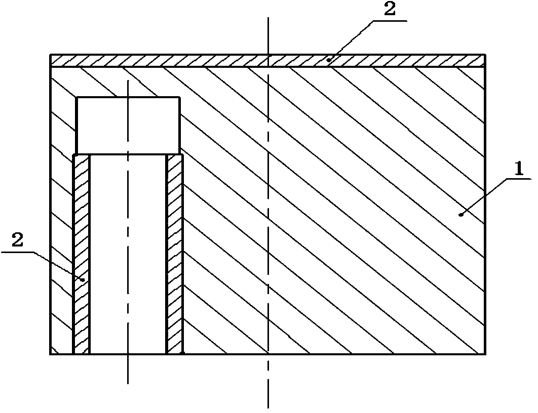
technical field [0001] The invention belongs to the field of metallurgical materials, in particular to a steel-steel bimetal rotor for a plunger hydraulic pump and a manufacturing method thereof. Background technique [0002] The plunger hydraulic pump relies on the reciprocating movement of the plunger in the rotor plunger chamber to change the volume of the plunger chamber to achieve oil suction and oil discharge. Because the plunger pump has the advantages of compact structure, high speed, large flow rate, high efficiency, high working pressure, and easy realization of variables, it is widely used in construction machinery, lifting transportation, metallurgy, ships, aerospace and other fields. [0003] The rotor is the key friction pair and heart part of the plunger hydraulic pump, such as figure 1 As shown, 1 is the steel substrate, and 2 is the anti-friction layer of self-lubricating wear-resistant steel. It bears alternating stress, impact load, surface friction and ...

Claims


Application Information

Patent Timeline
IPC IPC(8): F04B53/00C22C38/44C22C32/00C22C30/02B22F3/16B22F3/26B22F1/00
Inventor 陈广志王飞田玉清孙阳许庆森
Owner CENT IRON & STEEL RES INST
Learn More