
Deep recycling process and system for oily sludge

A technology for recycling and oil sludge, applied in the petroleum industry, sludge treatment, pyrolysis treatment of sludge, etc., can solve the problems of secondary pollution, incomplete disposal, high maintenance rate, and improve the dehydration rate and oil recovery. rate, realize resource utilization, and have the effect of broad prospects for utilization

Active Publication Date: 2015-09-02
福建省新环能环保科技有限公司
View PDF8 Cites 27 Cited by
  • Summary
  • Abstract
  • Description
  • Claims
  • Application Information

AI Technical Summary

Problems solved by technology

Direct dry distillation: too much energy consumption, high disposal costs
Tempering-mechanical dehydration: The mechanical dehydration device is easy to block, the maintenance rate is high, and the dehydrated cake needs to be transported for disposal, and the follow-up disposal cost is high
However, these disposal methods have problems such as incomplete disposal, easy to produce secondary pollution, high disposal cost, etc., and cannot fundamentally solve the problem of oily sludge disposal

Method used


Image

  • Deep recycling process and system for oily sludge
  • Deep recycling process and system for oily sludge

Examples


example 1

[0060] Floor sludge: oil content 14.5%, water content 19%, other solid content 66.5%. The processing capacity is 10m 3 (density 1.5t / m 3 ).

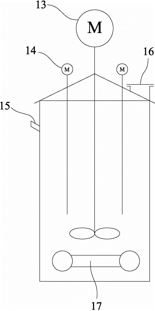
[0061] First, the 10 m 3 The ground sludge is sent from the storage yard to the conditioning tank. The temperature of the heating steam in the conditioning tank is 180 °C, and the temperature of the material in the tank is kept at 65 °C ~ 70 °C; the conditioning agent components are: demulsifier SP 2Kg, alum 4Kg, Cationic polyacrylamide 0.2Kg, clean water 1000Kg; put the conditioning agent into the conditioning tank, stir for 60 minutes, then start the vibrator for 30 minutes; after the vibration is completed, let the material stand for 60 minutes, start the water pump to extract conditioning The oil-water mixture in the upper part of the tank is 3850Kg, and the mixture is sent to the centrifugal separator for separation; the oily sludge in the lower part of the conditioning tank is pumped to the vacuum dehydrator for further drying, ...

example 2

[0063] Tank bottom sludge: oil content 53%, water content 25%, other solid content 22%. The processing capacity is 10m 3 (density 1.7t / m 3 ).

[0064] First, the 10 m 3 The oil sludge at the bottom of the tank is sent from the storage yard to the conditioning tank. The temperature of the heating steam in the conditioning tank is 180℃, and the temperature of the material in the tank is kept at 55℃~65℃; the conditioning agent components are: demulsifier SP 3Kg, alum 6Kg , cationic polyacrylamide 0.5Kg, clear water 2000Kg; put the conditioning agent into the conditioning tank, stir for 60 minutes, let it stand for 6 hours, start the water pump to extract the oil-water mixture in the upper part of the conditioning tank, and obtain a mixture of 8590Kg. The sludge is sent to the centrifugal separator for separation; the sludge in the lower part of the conditioning tank is pumped to the vacuum dehydrator for further drying, and the dehydrator feeds 5 m per batch. 3 , each feeding...


PUM


Abstract

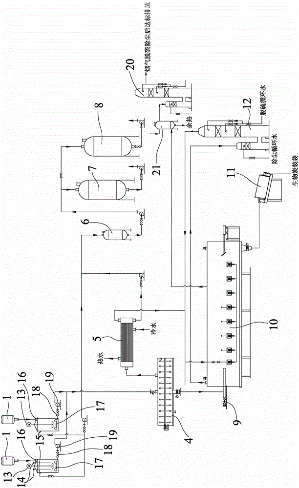
The invention discloses a deep recycling process for oily sludge. The process comprises the following steps: feeding oily sludge and a tempering agent into a tempering tank and uniformly stirring by using a heating device arranged in the tempering tank to realize oil-water-sludge three phase separation; separating an oil-water mixed solution into oil contents and water contents; feeding oily sludge into a vacuum dehydration machine; feeding the dehydrated oil sludge into a dry distillation furnace and performing dried distillation; purifying the dry distilled gas and feeding the purified dry distilled gas into a dry distilled furnace combustion chamber to be used as fuels; carbonizing the surplus sludge into biological carbon; cooling the biological carbon by a cooling device, wherein the cooled biological carbon can be used as a soil conditioner; performing the treatment on the dry distillation furnace flue gas to produce steam through an afterheat boiler to ensure that the steam is used for heating the tempering tank; and performing desulfuration and dust removal on the flue gas recycled by the afterheat to ensure that the flue gas meets the discharge standard. The invention also discloses a corresponding system which consists of the tempering tank, a mixed solution centrifugal separator, a vacuum dehydrator, a condenser, a spiral conveyor, a dry distilled furnace, a cooler and a dry distilled gas purification device. According to the deep recycling process and the deep recycling system, the pollution treatment is realized, and precious resources are recycled, so that the recycling for resources is realized.

Description

technical field [0001] The invention relates to a process and system for deep resource utilization of oily sludge, which belongs to environmental protection engineering technology. Background technique [0002] Oily sludge mainly comes from the ground oily sludge produced by crude oil extraction, the oily sludge at the bottom of tanks produced in the process of oil field gathering and transportation, and the oily sludge produced by the sewage treatment plant of the refinery. Landed oily sludge is the oil scattered on the ground in the oil production area or the oil leaked from the oil pipeline that has not entered the gathering and transportation pipeline during the oil production process. It is mixed with ground gravel, sediment, weeds, etc. During the oil production process In the process of well washing, operation discharge, wellhead spillage, accident discharge, etc., a large amount of landed oil sludge will be generated. Tank bottom sludge is the oily sludge deposits c...

Claims


Application Information

Patent Timeline
IPC IPC(8): C02F11/00C02F11/10C10B53/00
CPCY02W10/40
Inventor 陈良泽陈国叶
Owner 福建省新环能环保科技有限公司
Learn More