
Catalyst for electroless plating, metallic coating film produced using same, and method for producing said metallic coating film

A manufacturing method and catalyst technology, which are applied in physical/chemical process catalysts, chemical instruments and methods, liquid chemical plating, etc., can solve problems such as complicated processes, increased process costs, poor adhesion, etc., and achieve less risk of price changes, The effect of reducing process cost and reducing the number of steps

Active Publication Date: 2015-09-09
DIC CORP
View PDF8 Cites 7 Cited by
  • Summary
  • Abstract
  • Description
  • Claims
  • Application Information

AI Technical Summary

Problems solved by technology

[0005] That is, the method of first attaching the catalyst metal compound to the surface of the object to be plated and then converting it into reduced metal fine particles exhibiting a catalytic effect is common, but these methods have the following disadvantages: they need to go through two stages (impartment and activation) The process is a very complicated method. In addition, the process cost (process cost) increases due to the increase in the number of processes.
Since the silver colloidal particles prepared by this method contain tin oxide-based compounds, the catalyst particles and non-catalytic tin compounds compete for adsorption on the plated object, so there are the following disadvantages: it is difficult to make a sufficient catalyst amount evenly adsorbed on the ABS The surface of the plated object such as resin, epoxy resin, glass, ceramics, etc., is likely to become the cause of poor plating and poor adhesion when used in industry
[0009] In addition, in the colloidal catalyst system using a tin compound, a tin removal process is required before the plating process, which makes the process complicated. In addition, even after the removal process, inclusions such as chloride ions derived from the tin compound remain, Therefore, there is a problem that the formation of metal whiskers, ion migration after the formation of electronic circuits, and other concerns that damage the reliability of electronic circuits cannot be eliminated.

Method used

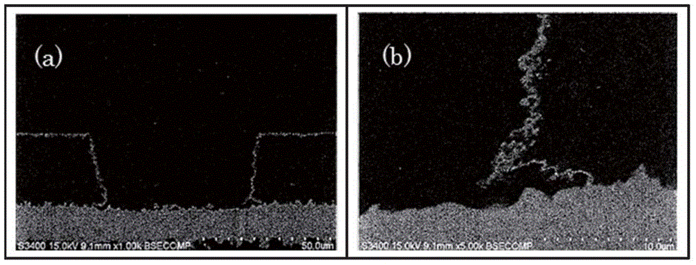
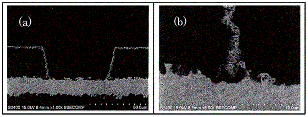

Image

  • Catalyst for electroless plating, metallic coating film produced using same, and method for producing said metallic coating film
  • Catalyst for electroless plating, metallic coating film produced using same, and method for producing said metallic coating film
  • Catalyst for electroless plating, metallic coating film produced using same, and method for producing said metallic coating film

Examples


Embodiment

[0096] Hereinafter, although an Example is given and this invention is demonstrated in detail, this invention is not limited to these. In addition, unless otherwise indicated, "part" and "%" are a mass basis.

[0097] The types of analysis equipment used in the present invention are as follows.

[0098] 1 H-NMR: Manufactured by JAPAN ELECTRON OPTICS LABORATORY CO.,LTD, AL300, 300Hz

[0099] TEM observation: manufactured by JAPAN ELECTRON OPTICS LABORATORY CO.,LTD, JEM-2200FS

[0100] Conductivity: HORIBA, Ltd. manufacture, B-173

[0101] SEM observation: S-3400 manufactured by HITACHI HIGH-TECHNOLOGIES CORPORATION

[0102] TG-DTA measurement: manufactured by SII NANOTECHNOLOGY INC., TG / DTA6300

[0103] Plasma absorption spectrum: manufactured by Hitachi, Ltd., UV-3500

[0104] Dynamic light scattering particle size measurement device: manufactured by OTSUKA ELECTRONICS Co., LTD, FPAR-1000

[0105] Surface resistivity measurement: manufactured by Mitsubishi Chemical Corpor...

Synthetic example 1

[0109]

[0110] (Synthesis of compound (X-1) having a phosphoric acid group)

[0111] Under a nitrogen atmosphere, 210 g of ethanol and 174 g of 2-butanone were added to the reaction container, and heated to 75° C. while stirring. To this, a mixed solution obtained by dissolving 600 g of Light Ester P-1M (manufactured by KYOEISHA CHEMICAL Co., LTD.) in a mixed solvent of 90 g of ethanol and 90 g of 2-butanone was added dropwise over 3.5 hours, and dropped simultaneously over 4.5 hours. A solution obtained by dissolving 3 g of a polymerization initiator "V-59" and 18 g of a chain transfer agent (methyl 3-mercaptopropionate) in 30 g of 2-butanone was added. After 21 hours from the start of the reaction, heating was stopped, and after air-cooling to room temperature, 300 g of distilled water was added. Remove the solvent by distillation under reduced pressure with a rotary evaporator, add 100 g of distilled water to remove by distillation under reduced pressure again, and filt...

Synthetic example 2

[0116]

[0117] (Synthesis of compound (X-2) having a carboxyl group)

[0118] 70 parts of methyl ethyl ketone (hereinafter referred to as MEK) was kept at 80°C in a nitrogen stream, and 10 parts of methacrylic acid, 10 parts of benzyl methacrylate, BLEMMER PME-1000 (manufactured by NOF CORPORATION) were added dropwise over 2 hours while stirring. ) 80 parts, 2 parts of thioglycolic acid, 80 parts of MEK, and 4 parts of a polymerization initiator (“Perbutyl (registered trademark) O”, manufactured by NOF CORPORATION). After completion|finish of dripping, 2 parts of "Perbutyl (registered trademark) O" was added, and it stirred at 80 degreeC for 22 hours more. Water was added to the obtained reaction mixture to remove the solvent under reduced pressure, and then the amount of non-volatile components was adjusted with water. Thus, an aqueous solution (33% of nonvolatile content) of a compound (X-2) having a carboxyl group as an anionic functional group was obtained. The resin ...


PUM

PropertyMeasurementUnit
Conductivityaaaaaaaaaa
Acid valueaaaaaaaaaa
Particle sizeaaaaaaaaaa

Abstract

The present invention provides: a catalyst for electroless plating, which is characterized by being a complex of a compound (X) and metal nanoparticles (Y), wherein the compound (X) is produced by polymerizing a monomer mixture (I) that contains a (meth)acrylic acid-type monomer having at least one anionic functional group selected from the group consisting of a carboxy group, a phosphoric acid group, a phosphorous acid group, a sulfonic acid group, a sulfinic acid group and a sulfenic acid group; a metallic coating film produced using the catalyst; and a method for producing a metallic coating film using the catalyst.

Description

technical field [0001] The present invention relates to a method for producing an electroless metal plating film using metal nanoparticles protected with an anionic compound, and an electroless plating catalyst suitable for the production method. Background technique [0002] Various noble metals are used as catalysts for electroless plating, and palladium is most widely used among them. However, the following two methods are mainly used as methods for attaching such noble metal catalysts to a plated object. [0003] (1) After the object to be plated is immersed in a sensitizer solution (hydrochloric acid solution of palladium chloride), the palladium salt is reduced on the object to be plated to obtain a palladium colloid attachment (sensitizer-activation method (sensitizer- activator process)). [0004] (2) The object to be plated is immersed in a tin-palladium mixed colloidal solution, and after the colloid is adsorbed on the object to be plated, it is immersed in an acc...

Claims


Application Information

Patent Timeline
IPC IPC(8): C23C18/18
CPCC23C18/18C23C18/1893C23C18/2086C23C18/38C23C18/30H05K3/181C23C18/1633B01J31/06B01J31/26B01J31/28C23C18/31
Inventor 深泽宪正新林昭太关根信博佐野义之森胁雅幸河村香大塚邦显姜俊行森口朋
Owner DIC CORP
Learn More