High-frequency electronic medium material

An electronic medium and high frequency technology, applied in the field of new electronic composite materials, can solve the problems of leakage current flow and conductivity loss, and achieve the effects of excellent heat resistance, uniform density and good compatibility

Active Publication Date: 2015-11-18
NANJING ANERTAI COMM SCI & TECH
View PDF4 Cites 0 Cited by
  • Summary
  • Abstract
  • Description
  • Claims
  • Application Information

AI Technical Summary

Problems solved by technology

Under the action of an electric field, there will be leakage current flowing in the medium, causing conductance loss

Method used


Image

  • High-frequency electronic medium material
  • High-frequency electronic medium material
  • High-frequency electronic medium material

Examples


Embodiment 1

[0029] The preparation of embodiment one filler

[0030] Disperse 1Kg of triphenylchlorosilane in deionized water, then add 500g of diethylmagnesium and 2092-ethyl-1-hexanol titanium; then conduct a hydrothermal reaction at 120°C for 3 hours; then filter the reaction solution and bake the filter cake After drying, calcinate at 600°C for 1 hour, cool naturally and then sinter at 950°C for 2 hours, add the obtained powder into ethanol, disperse evenly, then add 10g of polyoxyethylene sorbitan monooleate, and stir at 60°C for 2 hours , and finally dried to obtain a filler (particle size of 450nm to 680nm); 1000g of the filler was added to 1.6Kg of diglycidyl phthalate, and stirred at 125°C for 1 hour to obtain an active filler.

Embodiment 2

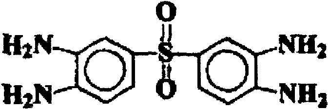
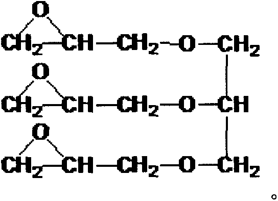
[0032] According to the composition of Table 1 and Table 2, proceed according to the following steps, mix cyclopentadienyl iron tricarbonyl and cyanate monomer, stir at 95°C for 10 minutes, then add amino compound and aliphatic glycidyl ether in turn, at 120 Stir for 1 hour at ℃, then add dipropylene phthalate, stir at 120°C for 0.5 hours, and obtain a resin prepolymer after cooling; then add the resin prepolymer to methyl ethyl ketone and stir for 1 hour; add active filler and propylene Nitrile; then add PMA and diallyl diphenyl ether, and continue to stir for 2.5 hours to obtain glue.

[0033] Table 1 raw material composition (g)

[0034]

[0035] Table 2 raw material composition (g)

[0036]

[0037] Acrylonitrile

Embodiment 3

[0038] Example 3 Preparation of high-frequency electronic dielectric material

[0039] Coat the above glue with electronic grade glass cloth and bake in an oven at 170°C for 2 minutes to prepare a prepreg; cut off the burrs of the prepreg; take 5 pieces of lamination and cover both sides with a release film, The high-frequency electronic dielectric material can be obtained by hot pressing.

[0040] The conditions of hot pressing adopt the method of gradually increasing temperature and increasing pressure. The temperature is raised from 50°C to 180°C for 10 minutes, kept for 60 minutes, then raised to 200°C for 10 minutes, kept for 90 minutes, then raised to 230°C for 5 minutes, kept for 90 minutes, and finally cooled to 50°C for 180 minutes. ; 1min pressure from 0Kg / cm 2 Rise to 15Kg / cm 2 , then keep the pressure for 45min, then rise to 20Kg / cm in 1min 2 Keep the pressure for 50 minutes, and rise to 35Kg / cm in the last 1 minute 2 , keep the pressure for 200min.


PUM

PropertyMeasurementUnit
Particle sizeaaaaaaaaaa

Abstract

The invention relates to a high-frequency electronic medium material. The material is manufactured in the mode that a reinforcing material is coated with glue and then hot-pressed. The glue preparation method includes the steps that triphenylsilyl chloride is dispersed in deionized water, then diethyl magnesium and 2-ethyl-1-hexanol titanium are added, then sorbitan monooleate ethoxylate is added, and filler is obtained; the filler is added into phthalic diglycidyl ester, and active filler is obtained; cyclopentadienyl iron tricarbonyl and a cyanate ester monomer are mixed, then an amino compound, aliphatic glycidol ether and diallyl phthalate are sequentially added, and resin prepolymer is obtained after cooling; then, the resin prepolymer is added into butanone and stirred; the active filler and acrylonitrile are added; PMA and diallyl diphenyl ether are added and continuously stirred to obtain a glue solution. The prepared high-frequency electronic medium material has excellent mechanical properties and heat resistance, and the requirements of development and application of the high-frequency electronic medium material are met.

Description

technical field [0001] The invention belongs to the technical field of novel electronic composite materials, and in particular relates to a high-frequency electronic dielectric material with excellent dielectric properties. Background technique [0002] The development and research of new materials is the forerunner of the development of materials science. Composite material is a new type of material. It has been widely used in aviation, aerospace, energy, transportation, machinery, construction, etc. in the past 30 years due to its diverse functions and excellent performance such as voltage resistance, light weight, designability, high temperature resistance, and folding resistance. , chemical industry, biomedicine and sports and other fields. With the development and application of materials, composite materials have formed a network and penetrated into various industries. Under the action of an electric field, the transformation from electrical energy to other forms of ...

Claims


Application Information

Patent Timeline
IPC IPC(8): C08L79/04C08L63/00C08G73/06C08G59/58C08G59/32C08K9/04C08K5/00C08K7/14
CPCC08G59/32C08G59/58C08G73/0644C08K5/0091C08K7/14C08K9/08C08L2201/08C08L2203/20C08L79/04C08L63/00
Inventor 彭代信宋晓静张新建
Owner NANJING ANERTAI COMM SCI & TECH
Why Eureka
Try Eureka