
Thermal barrier coating for turbine blade assembly and preparation method thereof

A technology of turbine blades and thermal barrier coatings, applied in the field of surface coatings containing ceramic layers and its preparation, can solve the problems of affecting thermal fatigue performance of holes, accelerating crack extension, sintering around ceramic outer layer holes, etc., to achieve long-term maintenance Stable work, improved resistance to high temperature oxidation, and improved service life

Active Publication Date: 2019-09-27
BEIJING HUAQING GAS TURBINE & INTEGRATED GASIFICATION COMBINED CYCLE ENG TECH
View PDF7 Cites 0 Cited by
  • Summary
  • Abstract
  • Description
  • Claims
  • Application Information

AI Technical Summary

Problems solved by technology

The atmosphere containing carbon and other impurities generated in these two processes will inevitably remain in the base material near the cooling hole, reducing the oxidation resistance, thermal corrosion resistance and even mechanical properties of the base material surface.
In the second solution, the laser can only ablate the outer layer of the ceramic, and will produce a certain thickness of remelted layer, which will affect the thermal fatigue performance of the hole
In addition, the blade often needs to be clamped twice on different machine tools, and the positioning is prone to deviation
In the third scheme, sintering and spalling around the hole of the ceramic outer layer are easy to occur, and a thick recast layer is easy to occur around the hole of the metal bonding layer and the substrate, which is easy to induce thermal fatigue cracks and accelerate crack extension and growth.

Method used


Image

  • Thermal barrier coating for turbine blade assembly and preparation method thereof
  • Thermal barrier coating for turbine blade assembly and preparation method thereof
  • Thermal barrier coating for turbine blade assembly and preparation method thereof

Examples


Embodiment 1

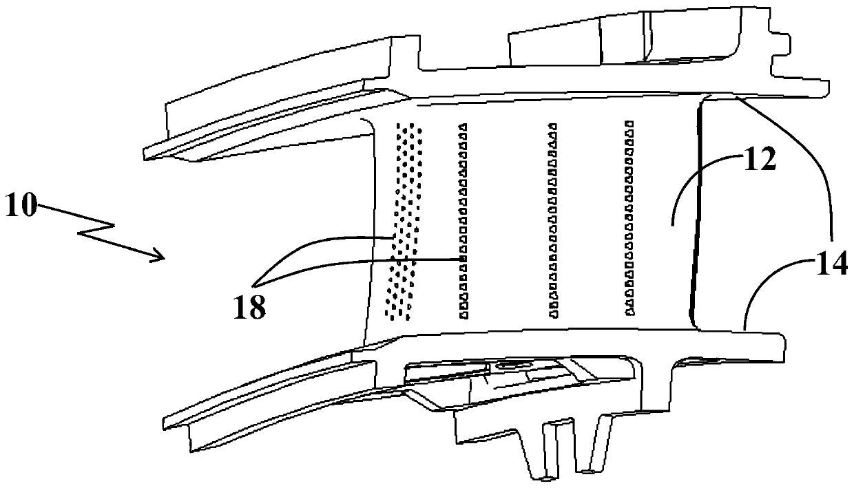
[0047] figure 1 is a perspective view of a turbine blade. The overall turbine blade 10 includes an airfoil 12 , an edge plate 14 (including upper and lower edge plates) and cooling holes 18 .

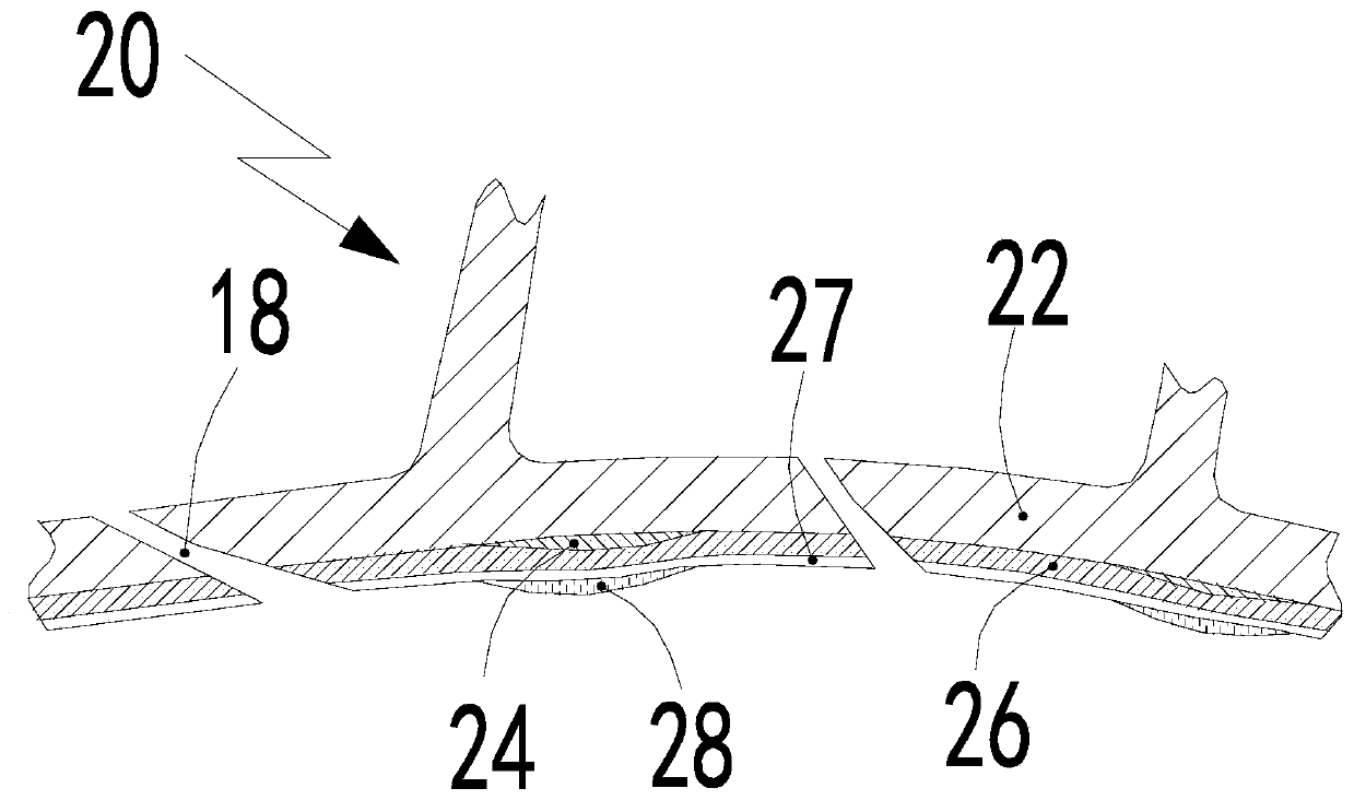
[0048] See figure 2 , this embodiment discloses a thermal barrier coating system for a superalloy substrate. The matrix is ​​a gas turbine guide vane assembly, which mainly serves to provide sufficient strength under high temperature and mixed gas atmosphere, and acts as a structural part. The preparation process of each layer system of the coating mainly includes:

[0049] In the first step, a partial MCrAlY bonding layer is prepared. The selection principle of the application area of ​​the adhesive layer is: firstly, exclude the peripheral area of ​​the cooling hole, and the specific excluded area is the area within about 10 mm on the left and right sides of the cooling hole array. Then select several areas where the temperature of the outer surface of the blade body and the edg...

Embodiment 2

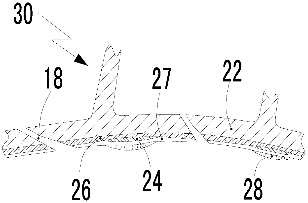
[0058] See image 3 . The matrix is ​​a gas turbine guide vane assembly, which mainly serves to provide sufficient strength under high temperature and mixed gas atmosphere, and acts as a structural part. The coating process on the guide vane assembly overall 30 is:

[0059] In the first step, a chemical vapor deposition treatment is applied to the entire airfoil and the outer surface area of ​​the edge plate.

[0060] For the aluminide layer 26 in this embodiment, a platinum-modified aluminide coating is prepared by a typical chemical vapor deposition process in which reaction gases are mixed externally and then fed into the chamber. The specific process steps are as follows: first, a layer of platinum-nickel alloy is electrochemically deposited on the surface of the substrate 22, and then platinum diffusion annealing is performed before chemical vapor deposition aluminizing. The gas phase interface is the β-NiAl sublayer in solid solution of platinum, and the point-like se...


PUM

PropertyMeasurementUnit
thicknessaaaaaaaaaa
thicknessaaaaaaaaaa
thicknessaaaaaaaaaa

Abstract

The invention provides a turbine blade assembly thermal barrier coating. The turbine blade assembly thermal barrier coating comprises a bonding layer, an aluminide layer, an aluminum oxide layer and a ceramic layer which are sequentially arranged in an upward mode from a turbine blade assembly base material or comprises an aluminide layer, a bonding layer, an aluminum oxide layer and a ceramic layer which are sequentially arranged. The bonding layer is a MCrAlY layer, and M represents one or two or three sorts of nickel, cobalt and iron. According to the thermal barrier coating system provided by the invention, the high-temperature oxidation resistance, thermal corrosion resistance and endurance property of the thermal barrier coating are improved on the premise that the thermal barrier effect of the thermal barrier coating is guaranteed, and thus the service life of a turbine blade assembly is prolonged. By means of the thermal barrier coating system prepared through the method, the weight of the blade assembly can be lowered obviously, and therefore the creep degree of the assembly by tension of the turbine blade assembly in the high-speed rotating process is decreased and the service life of the turbine blade assembly is prolonged.

Description

technical field [0001] The invention belongs to the field of surface treatment of metal materials, and in particular relates to a surface coating containing a ceramic layer and a preparation method thereof. Background technique [0002] A gas turbine is a well-developed and widely used mechanical device that converts the chemical energy of fuel into heat and mechanical energy to drive equipment or facilities such as jet aircraft, large ships, generator sets, and fluid pumps. In order to improve energy utilization efficiency, the metal materials used for the hot end parts of gas turbines are often close to or reach the critical state of their thermal stability when the equipment is working, that is, in order to improve the efficiency of gas turbines, the temperature of the turbine inlet is greatly increased. In fact, the first stage moving and guide vanes of advanced gas turbines are often in a mixed gas atmosphere higher than their melting point when they work. Only because...

Claims


Application Information

Patent Timeline
Patent Type & Authority Patents(China)
IPC IPC(8): C23C28/00
CPCC23C28/3215C23C28/345Y02T50/60
Inventor 于大千段方苗张涛刘伟
Owner BEIJING HUAQING GAS TURBINE & INTEGRATED GASIFICATION COMBINED CYCLE ENG TECH
Learn More