Production method and production system of dimethyl dicarbonate

A technology of dimethyl dicarbonate and production method, which is applied in the direction of purification/separation of carbonate/haloformate, preparation of carbonate/haloformate, chemical instruments and methods, etc., and can solve the increase target Product and water contact time, reducing reaction conversion rate and other issues, to achieve the effect of increasing the yield of target substances, increasing conversion rate, and shortening the process flow

Active Publication Date: 2018-06-22
宁波斯特莱生物技术有限公司
View PDF2 Cites 0 Cited by
  • Summary
  • Abstract
  • Description
  • Claims
  • Application Information

AI Technical Summary

Problems solved by technology

Dimethyl dicarbonate is easy to hydrolyze, and the reaction time is more than 1 hour, which increases

Method used


Image

  • Production method and production system of dimethyl dicarbonate

Examples


Embodiment 1

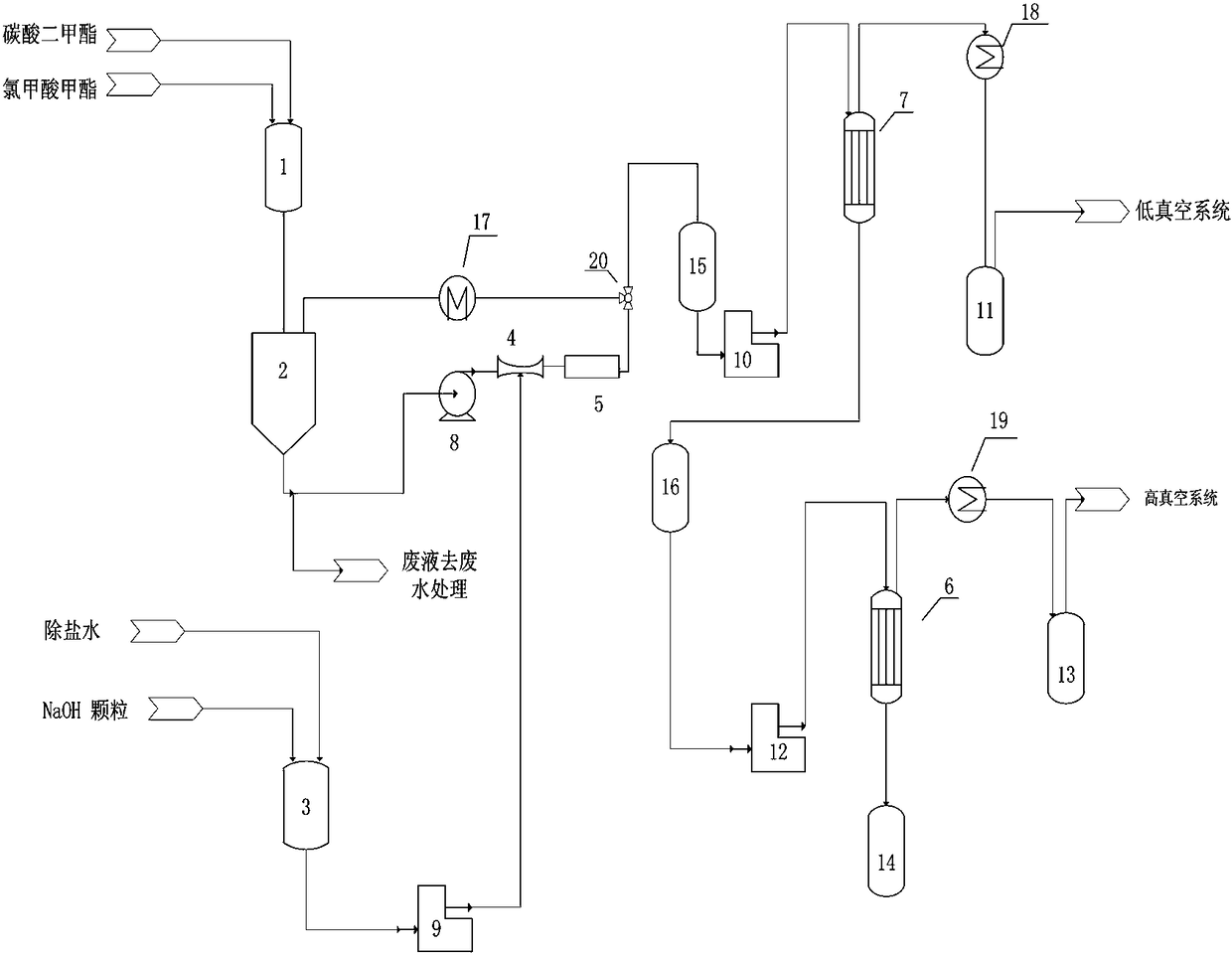
[0028] A kind of production method of dimethyl dicarbonate, such as figure 1shown, including the following steps:

[0029] (1) Add methyl chloroformate, solvent and catalyst into feeding tank 1 in a mass ratio of 1:1:0.02 and mix evenly to obtain a mixed reaction material; wherein the solvent is selected from dimethyl carbonate, methylene chloride and xylene At least one of the catalysts selected from dodecyl dimethyl benzyl ammonium chloride, three - (dodecyl) methyl ammonium chloride, tris - (tetradecyl) methyl ammonium chloride and At least one of tetra-(octaalkyl)ammonium chloride;

[0030] (2) Send the mixed reaction materials into the reaction buffer tank 2 with oil-water separation function, control the temperature in the reaction buffer tank 2 to be 0-15°C, and send the mixed reaction materials through the material circulation pump 8 and the Venturi tube 4 in turn In the static mixing reactor 5, the sodium hydroxide solution that will come from the mass concentration...

Embodiment 2

[0035] With above-mentioned embodiment 1, its difference is:

[0036] In step (1), the mass ratio of methyl chloroformate, solvent and catalyst is 1:0.5:0.005;

[0037] In step (2), the molar ratio of sodium hydroxide to methyl chloroformate is 1:1.0;

[0038] In step (3), the absolute pressure of the low-vacuum evaporator 6 is controlled to be 10 kpa, and the evaporation temperature is 35°C;

[0039] In step (4), the absolute pressure of the high vacuum evaporator 7 is controlled to be 190 pa, the distillation temperature is 25°C, and the purity of the obtained dimethyl dicarbonate product is 99.90%.

Embodiment 3

[0041] With above-mentioned embodiment 1, its difference is:

[0042] In step (1), the mass ratio of methyl chloroformate, solvent and catalyst is 1:0.5:0.005;

[0043] In step (2), the molar ratio of sodium hydroxide to methyl chloroformate is 1:1.0;

[0044] In step (3), the absolute pressure of the low-vacuum evaporator 6 is controlled to be 3kpa, and the evaporation temperature is 10°C;

[0045] In step (4), the absolute pressure of the high-vacuum evaporator 7 is controlled to 60 pa, the distillation temperature is 10°C, and the purity of the obtained dimethyl dicarbonate product is 99.90%.


PUM


Abstract

The invention discloses a production method and a production system of dimethyl dicarbonate. The production method comprises the steps that methylchloroformate, a solvent and a catalyst are added intoa feeding tank and then sent into a reaction buffer tank to be mixed uniformly; the reaction mixture and a sodium hydroxide solution from an alkali preparation tank are sent into a static mixed reactor to be subjected to a mixed reaction, the obtained reaction product is sent into the reaction buffer tank to be subjected to oil-water separation; the oil phase obtained through separation is sent into a rough vacuum evaporator; and a rough product is sent into a high vacuum evaporator to react, and a dimethyl dicarbonate product with the purity being 99.9% or above is obtained. The production system comprises the feeding tank, the alkali preparation tank, the reaction buffer tank, a Venturi tube, the static mixed reactor, an oil-water separator, the rough vacuum evaporator and the high vacuum evaporator, and has the advantages that the conversion rate is high, the product purity is high, and the production system is suitable for large-scale industrial production.

Description

technical field [0001] The invention relates to a production method of dimethyl dicarbonate and a production system thereof. Background technique [0002] Dimethyl dicarbonate belongs to a self-decomposing fungicide that can complete sterilization at room temperature and decompose rapidly in a short period of time. It is mainly used for antiseptic sterilization of beverages and low-concentration alcoholic beverages. In general, non-alcoholic beverages spoil easily. Fruit juices, sugars, thickeners and other ingredients are ideal culture media for food spoilage bacteria such as yeasts, molds and fermentative bacteria. This is due to the presence of microorganisms in all aspects of the production of beverages, such as in the surrounding air, on the production equipment, and even in the beverage itself. In beverage production, in order to prolong the shelf life of the product, it is necessary to select a suitable method to sterilize the beverage. The sterilization measures...

Claims


Application Information

Patent Timeline
IPC IPC(8): C07C68/00C07C68/08C07C69/96
CPCC07C68/00C07C68/08C07C69/96
Inventor 安靖东
Owner 宁波斯特莱生物技术有限公司
Why Eureka
Try Eureka