Manufacturing method for semi-solid aluminum electrolytic capacitor

A technology for aluminum electrolytic capacitors and manufacturing methods, applied in capacitor manufacturing, capacitors, wire wound capacitor machines, etc., can solve problems such as LC increase, anode foil oxide film loss of self-repair function, etc., to suppress LC increase and increase capacity Effect of lead-out rate and high-capacity characteristics

Inactive Publication Date: 2018-09-14
CAPXON ELECTRONIC (SHENZHEN) CO LTD
View PDF4 Cites 9 Cited by
  • Summary
  • Abstract
  • Description
  • Claims
  • Application Information

AI Technical Summary

Problems solved by technology

However, if the use time exceeds the life guarantee period, the capacitor will eventually disappear due to the volatilization of the solvent of the electrolyte, and the oxide film of the anode foil will also lose

Method used


Image

  • Manufacturing method for semi-solid aluminum electrolytic capacitor
  • Manufacturing method for semi-solid aluminum electrolytic capacitor
  • Manufacturing method for semi-solid aluminum electrolytic capacitor

Examples


Embodiment 1

[0032] This embodiment includes the following steps:

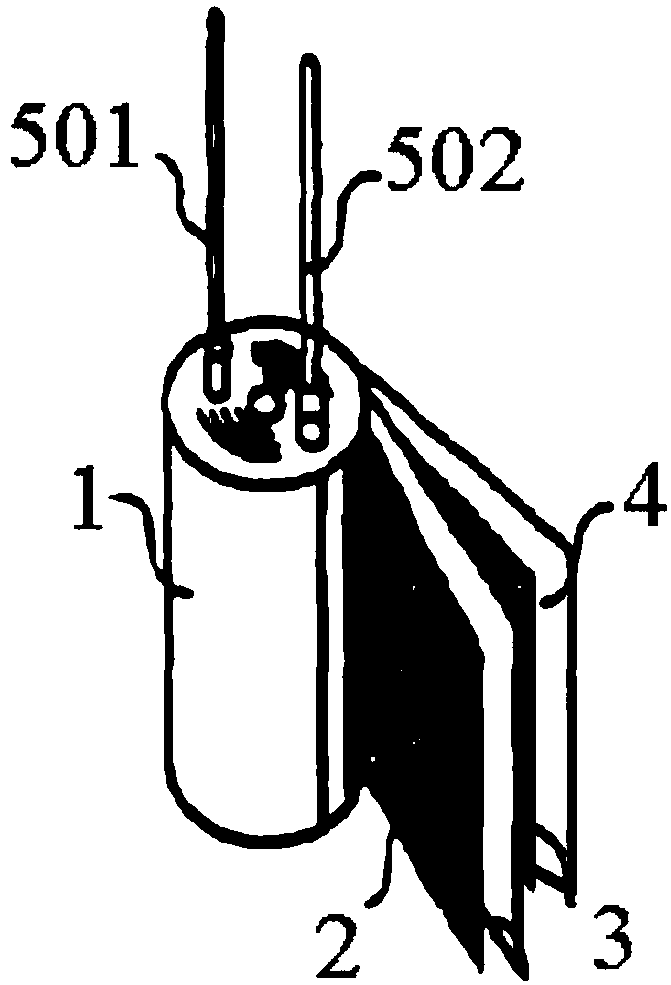
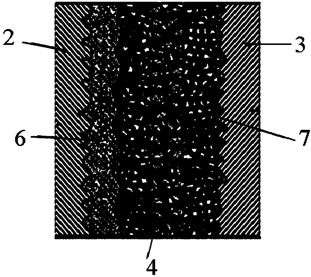
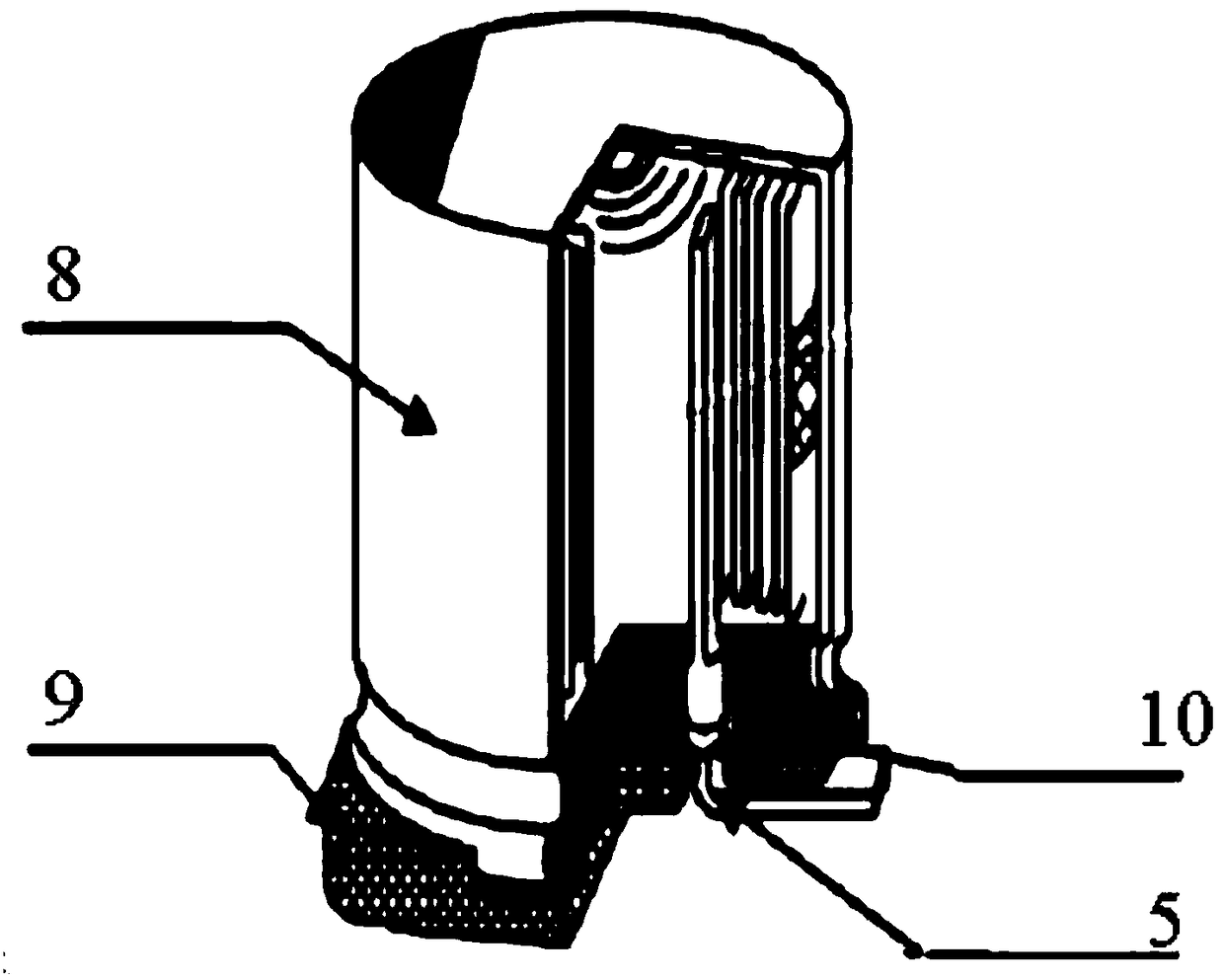
[0033]A1. To make the element, cut the positive foil, negative foil and electrolytic paper according to the designed size through a nailing machine, then rivet the positive guide pin and the negative guide pin on the positive foil and the negative foil respectively, and then clip the positive foil and the negative foil The electrolytic paper is wound into a circle, and finally the outer periphery of the circle is wrapped with high-temperature-resistant insulating tape to fix it to form a prime;

[0034] A2. The first impregnation stage. In this stage, the element is impregnated with the low-pressure chemical solution of the adipic acid system. By applying a voltage of 110V to the guide wire, the current density is 0.05mA / pcs, and the surface of the positive foil is oxidized due to cutting and nailing. Repair the defective part of the skin;

[0035] A3. The second impregnation stage. At this stage, the element is impregnat...

Embodiment 2

[0043] The steps and principles of this embodiment are basically the same as those of Embodiment 1, except that the dispersion liquid in the above-mentioned step A3 includes 2% polyethylenedioxythiophene and 4% polystyrene with an average molecular weight of 100,000, calculated by weight percentage. Ethylene sulfonic acid, 0.5% toluene sulfonic acid.

[0044] The processing liquid in A4 comprises the polyethylene glycol amount that molecular weight is 200, calculates by weight percentage, polyethylene glycol (PEG) 35%, ethylene glycol (EG) 15%, gamma-butyrolactone 10% (GBL) , 15% ethanol, 20% water and 5% phthalic acid.

[0045] The electrolytic solution in A5 comprises by weight percent, 25% phthalic acid, tetramethylimidazole, pyridine acid γ-butyrolactone and sulfonic acid mixed solvent, the weight ratio of γ-butyrolactone and sulfonic acid 1:1.


PUM

PropertyMeasurementUnit
Boiling pointaaaaaaaaaa

Abstract

The invention proposes a manufacturing method for a semi-solid aluminum electrolytic capacitor, and relates to the technical field of aluminum electrolytic capacitors. The method comprises the following steps: S100, the making of an element; S200, a first impregnation stage, wherein the element is impregnated into a liquid at the stage; S300, a second impregnation stage, wherein the element is impregnated with a conductive polymer monomer, an oxidant and dispersion liquid at the stage; S400, a third impregnation stage, at which the element is impregnated with a treatment liquid; S500, a fourthimpregnation stage, at which the element is impregnated with an electrolyte; S600, the packaging of the element which is subjected to the fourth impregnation stage into an aluminum shell. In the invention, a mixed aluminum electrolytic capacitor (the semi-solid aluminum electrolytic capacitor) which contains the three materials (a conductive solid layer, treating fluid and the electrolyte) and isformed by the conductive polymers is disposed in the capacitor element. The semi-solid aluminum electrolytic capacitor has the characteristics of high reliability, high capacity, high ripple currentresistance and the like, has the function of promoting the repair of the defect portion of an oxide film of anode foil, and can suppress the occurrence of a short circuit fault.

Description

technical field [0001] The invention relates to the technical field of aluminum electrolytic capacitors, in particular to a method for manufacturing a semi-solid aluminum electrolytic capacitor. Background technique [0002] With the digitalization of electronic products, those current output circuits, especially in the field of AV equipment and automotive devices, are increasingly demanding high reliability, requiring their performance such as miniaturization, high capacity, low ESR, and low LC. There are also special requirements for short-circuit resistance. Compared with solid-state electrolytic capacitors, liquid aluminum electrolytic capacitors have the advantage that the electrolyte can repair the defective part of the oxide film of the anode foil and suppress the occurrence of short-circuits. Even if the solvent of the electrolyte is gone due to volatilization, there is electrolytic paper insulation between the oxidizable film and the negative foil, so the failure mo...

Claims


Application Information

Patent Timeline
IPC IPC(8): H01G13/00H01G13/02H01G13/04H01G9/022
CPCH01G13/003H01G9/022H01G13/006H01G13/02H01G13/04
Inventor 杨振毅林金村
Owner CAPXON ELECTRONIC (SHENZHEN) CO LTD
Why Eureka
Try Eureka