
Near-infrared second-region fluorescent compound with aggregation-induced luminescent properties, preparation method, nanoparticle micelles and application thereof

A technology of aggregation-induced luminescence and fluorescent compounds, which is applied in the field of biomedical fluorescence imaging, can solve the problems of low luminous efficiency, narrowing the molecular distance, and limiting the application of dyes, etc., achieving good imaging effects, good biocompatibility, and broad application prospects Effect

Active Publication Date: 2020-09-25
SHENZHEN RES INST OF WUHAN UNIVERISTY
View PDF7 Cites 0 Cited by
  • Summary
  • Abstract
  • Description
  • Claims
  • Application Information

AI Technical Summary

Problems solved by technology

[0004] Many fluorescent materials in the second near-infrared region are mostly rigid planar molecules with large conjugated systems, and have high fluorescence quantum yields in dilute organic solutions, but fluorescent materials in the second near-infrared region are often in the form of nanoparticles or aqueous solutions Putting it into practical applications, the distance between molecules is reduced, and the aromatic rings of adjacent molecules are piled up, which inhibits the radiative decay of the excited state, resulting in a decrease in luminous efficiency or even no luminescence. This phenomenon is called aggregation-induced fluorescence quenching (Aggregation-induced fluorescence quenching). -Caused Quenching, ACQ), this property limits the application of near-infrared second region dyes in bio-optical imaging

Method used


Image

  • Near-infrared second-region fluorescent compound with aggregation-induced luminescent properties, preparation method, nanoparticle micelles and application thereof
  • Near-infrared second-region fluorescent compound with aggregation-induced luminescent properties, preparation method, nanoparticle micelles and application thereof
  • Near-infrared second-region fluorescent compound with aggregation-induced luminescent properties, preparation method, nanoparticle micelles and application thereof

Examples


preparation example Construction

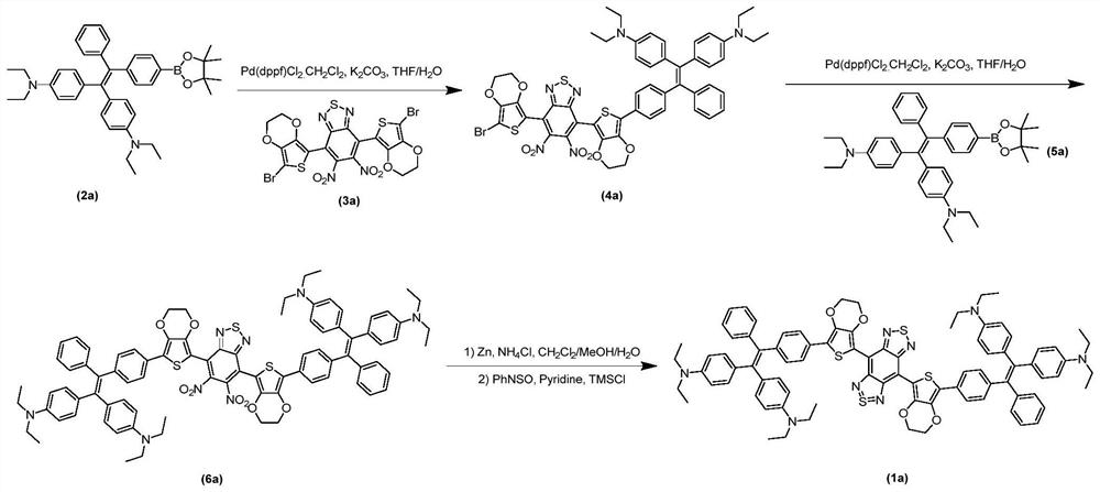
[0043] combined with Figures 1 to 10 As shown, a preparation method of the above-mentioned near-infrared two-region fluorescent compound with aggregation-induced luminescence properties includes the following route:

[0044]

[0045] The reaction conditions are:

[0046] a Under the protection of nitrogen or argon inert gas, add compound 2 and compound 3 into a reaction vessel, add tetrahydrofuran to dissolve the compounds, then pass argon or nitrogen into the reaction solution to remove oxygen in the system, add potassium carbonate aqueous solution dropwise, Weigh [1,1'-bis(diphenylphosphino)ferrocene]palladium dichloride dichloromethane complex and add it, and heat the reaction in an oil bath at 66°C-80°C under the protection of nitrogen or argon for 8 -24 hours, intermediate 4 was purified after the reaction;

[0047] b Under the protection of nitrogen or argon inert gas, take intermediate 4 and compound 5 and add them to the reaction vessel, add tetrahydrofuran to di...

Embodiment 1

[0052] Embodiment 1: the preparation of compound 4a

[0053] Take compound 2a (194mg, 0.33mmol), compound 3a (204mg, 0.31mmol) and potassium carbonate (85mg, 0.62mmol) into a 100mL round bottom flask, add tetrahydrofuran-water (v / v, 5: 1) 20mL, feed argon into the reaction solution and bubble for 5min to remove the oxygen in the system, add [1,1'-bis(diphenylphosphino)ferrocene]dichloropalladium dichloromethane complex (50mg , 0.06 mmol), under the protection of argon, heated to reflux in an oil bath at 75°C for 10 hours. After the reaction, cool to room temperature, remove THF by rotary evaporation, redissolve the residue in 70 mL of dichloromethane, wash with water (40 mL×3) three times, and wash with saturated brine (40 mL×3) three times. The organic phase was dried with anhydrous magnesium sulfate for 3 hours, filtered, and the filtrate was spin-dried to obtain 334 mg of compound 4a. Yield: 75%.

[0054] The structure determination data of compound 4a are as follows:

...

Embodiment 2

[0056] Embodiment 2: the preparation of compound 6a

[0057] Take compound 4a (334mg, 0.32mmol), compound 5a (194mg, 0.33mmol) and potassium carbonate (88mg, 0.64mmol) into a 100mL round bottom flask, add tetrahydrofuran-water (v / v, 5: 1) 20mL, feed argon into the reaction solution and bubble for 5min to remove the oxygen in the system, add [1,1'-bis(diphenylphosphino)ferrocene]dichloropalladium dichloromethane complex (50mg , 0.06 mmol), under the protection of argon, heated to reflux in an oil bath at 75°C for 14 hours. After the reaction, cool to room temperature, remove THF by rotary evaporation, redissolve the residue in 70 mL of dichloromethane, wash with water (40 mL×3) three times, and wash with saturated brine (40 mL×3) three times. The organic phase was dried with anhydrous magnesium sulfate for 3 hours, filtered, and the filtrate was spin-dried to obtain 345 mg of compound 6a. Yield: 72%.

[0058] The structure determination data of compound 6a are as follows:

...


PUM

PropertyMeasurementUnit
particle diameteraaaaaaaaaa
emission peakaaaaaaaaaa

Abstract

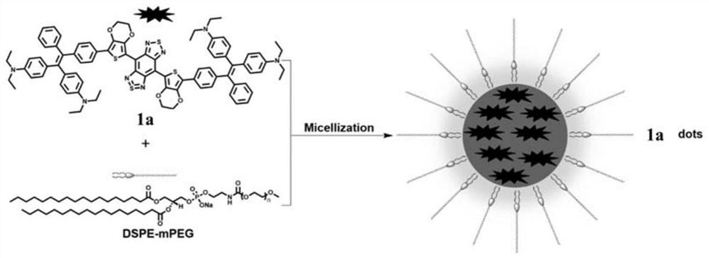
The invention discloses a near-infrared region II fluorescent compound with an aggregation induced emission property, a preparation method, a nanoparticle micelle and an application of the nanoparticle micelle. The near-infrared region II aggregation induced emission fluorescent compound is an organic micromolecular compound, is large in Stokes shift, has strong fluorescence emission and can effectively overcome the defect of aggregation induced quenching of the traditional fluorescent dye. The fluorescent compound is entrapped by distearoyl phosphatidyl ethanolamine-polyethylene glycol to form the nano micelle; a prepared fluorescence probe has the advantages of good water solubility and biocompatibility, no toxicity, relatively high light stability, and very high biological imaging signal to noise ratio and sensitivity. The fluorescence probe can be used as a near-infrared region II report material for disease diagnosis, intraoperative navigation treatment, tissue and organ functionevaluation and the like, can play an important role in medical optical examination in the future and has very good application prospects.

Description

technical field [0001] The invention belongs to the technical field of biomedical fluorescence imaging applications, and in particular relates to a near-infrared second-region fluorescent compound with aggregation-induced luminescent properties, a preparation method, nanoparticle micelles and applications thereof. Background technique [0002] Bio-optical imaging refers to the method of using optical detection means combined with optical detection molecules to image cells or tissues or even organisms to obtain biological information. If bio-optical imaging is limited to the range of visible light and near-infrared light, bio-optical imaging can be divided into fluorescence imaging, bioluminescence imaging, photoacoustic imaging, optical tomography, etc. according to different detection methods. Fluorescent imaging technology uses fluorescent reporter groups, including inorganic materials, such as upconversion, quantum dots, etc., organic materials, such as green fluorescent ...

Claims


Application Information

Patent Timeline
Patent Type & Authority Patents(China)
IPC IPC(8): C07D519/00C09K11/06C09K11/02B82Y20/00B82Y30/00B82Y40/00G01N21/64G01N21/84G01N21/33
CPCB82Y20/00B82Y30/00B82Y40/00C07D519/00C09K11/025C09K11/06C09K2211/1007C09K2211/1051C09K2211/1088C09K2211/1092G01N21/33G01N21/6428G01N21/84
Inventor 洪学传肖玉玲曾小东林嘉诚
Owner SHENZHEN RES INST OF WUHAN UNIVERISTY
Learn More