
Manufacturing method of gate-all-around transistor

A transistor and gate-all-around technology, applied in the field of preparation of gate-around transistors, can solve the problems of low process stability and the like

Active Publication Date: 2021-08-20
SHANGHAI INST OF MICROSYSTEM & INFORMATION TECH CHINESE ACAD OF SCI
View PDF6 Cites 0 Cited by
  • Summary
  • Abstract
  • Description
  • Claims
  • Application Information

AI Technical Summary

Problems solved by technology

[0015] In view of the shortcomings of the prior art described above, the purpose of the present invention is to provide a method for preparing a gate-all-round transistor, which is used to solve the problem of low process stability in the preparation of a gate-all-around transistor in the prior art

Method used


Image

  • Manufacturing method of gate-all-around transistor
  • Manufacturing method of gate-all-around transistor
  • Manufacturing method of gate-all-around transistor

Examples


Embodiment 1

[0055] Such as Figure 15 ~ Figure 21 and Figure 29 ~ Figure 50 As shown, this embodiment provides a method for manufacturing a gate-all-round transistor, and the method includes:

[0056] Such as Figure 15 As shown, first carry out step 1), provide the first silicon substrate 201 and the second silicon substrate 301, form the first insulating layer 202 on the surface of the first silicon substrate 201, and form the first insulating layer 202 on the surface of the second silicon substrate 301 A second insulating layer 302 is formed on the surface. Certainly, in other embodiments, the first silicon substrate and the second silicon substrate may also be other semiconductor materials, for example, the materials of the first semiconductor substrate and the second semiconductor substrate may be It is one of germanium, silicon germanium, gallium nitride, aluminum nitride, gallium arsenide, silicon carbide, zinc oxide, gallium oxide, and indium phosphide, and is not limited to t...

Embodiment 2

[0085] Such as Figure 22 to Figure 50 As shown, this embodiment provides a method for manufacturing a gate-all-round transistor, and the method includes:

[0086] Such as Figure 22 As shown, step 1) is performed first, providing a first silicon substrate 201 and a second silicon substrate 301 , and forming a first insulating layer 202 on the surface of the first silicon substrate 201 . Certainly, in other embodiments, the first silicon substrate and the second silicon substrate may also be made of other silicon materials, for example, the materials of the first semiconductor substrate and the second semiconductor substrate may be It is one of germanium, silicon germanium, gallium nitride, aluminum nitride, gallium arsenide, silicon carbide, zinc oxide, gallium oxide, and indium phosphide, and is not limited to the examples listed here.

[0087] For example, a silicon dioxide layer is formed on the surface of the first silicon substrate 201 by a thermal oxidation process as...


PUM

PropertyMeasurementUnit
thicknessaaaaaaaaaa
depthaaaaaaaaaa
thicknessaaaaaaaaaa

Abstract

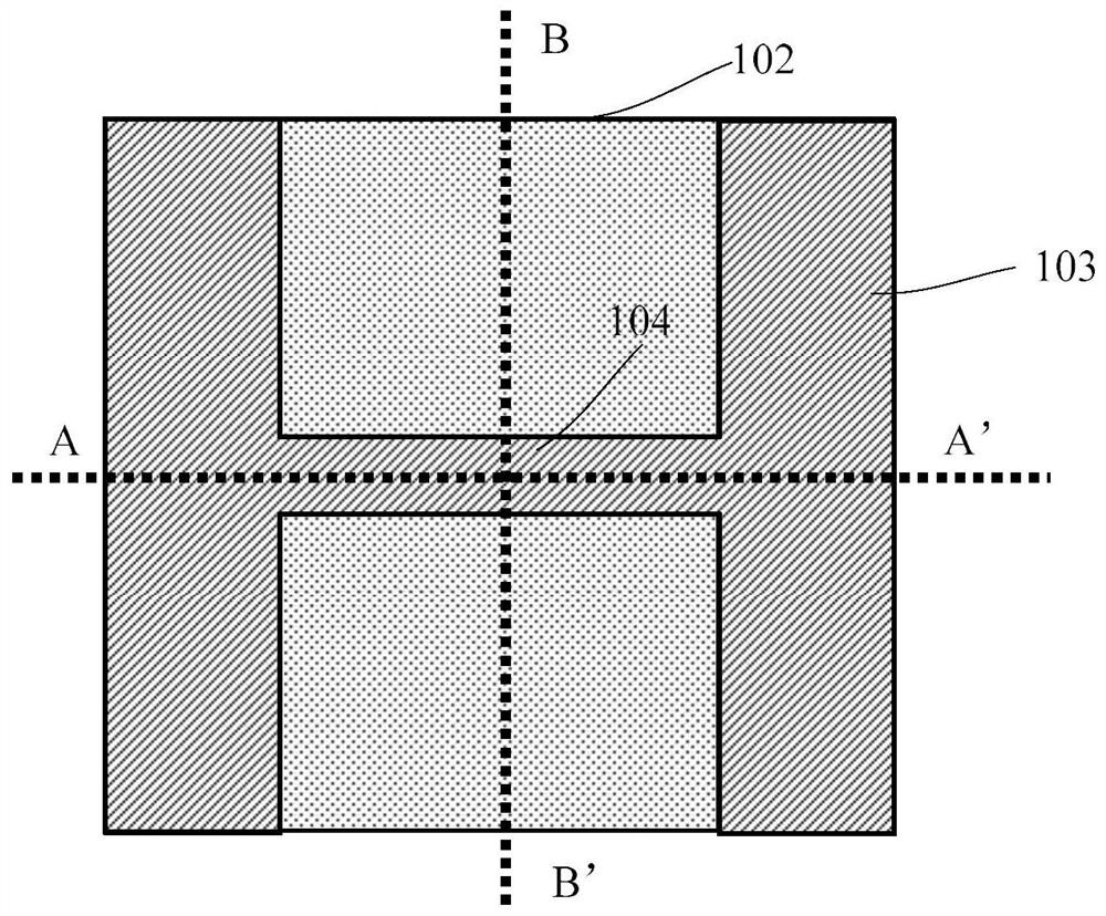
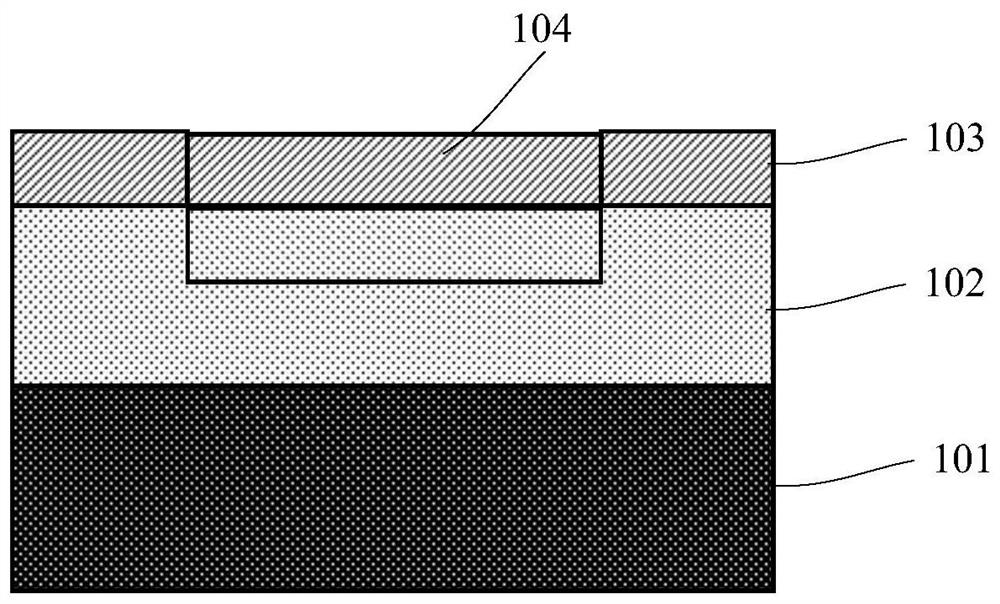
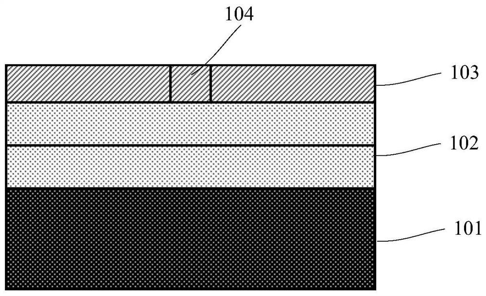
The invention provides a method for preparing a gate-all-around transistor, the method comprising: 1) providing an SOI substrate with a groove formed in its insulating layer; 2) forming a semiconductor nanowire structure suspended and straddling the groove; 3) Rounding and thinning the semiconductor nanowire structure; 4) forming an implantation barrier layer on the surface of the channel region, the implantation barrier layer reveals the preparation area of ​​the source region and the drain region; 5) performing an ion implantation process to form the source region and drain region; 6) forming a fully-enclosed gate dielectric layer and a gate electrode layer on the surface of the semiconductor nanowire, and patterning to form a gate structure; 7) forming a source electrode and a drain electrode. The gate-all-round transistor of the present invention is prepared by a gate-last process, which can effectively increase the selection range of gate materials, thereby realizing different device performance requirements. The invention does not need isotropic wet etching when preparing semiconductor nanowires, and can effectively avoid the generation of concave cavities.

Description

technical field [0001] The invention belongs to the field of design and manufacture of semiconductor integrated circuits, in particular to a preparation method of a gate-around transistor. Background technique [0002] As microelectronic devices continue to shrink, it is expected that the existing FinFET technology will face a large technical bottleneck at the 5nm and 3nm nodes, and the device performance will no longer be greatly improved as the device size continues to decrease. This requires us to adopt new device technologies, such as new device materials (such as strained silicon, silicon germanium, germanium, III-V semiconductors, etc.), and new device structures (such as nanowire gate-around transistors, etc.). [0003] The nanowire gate-all-around transistor can confine the conductive channel to the center of the nanowire, rather than the interface between the nanowire and the gate oxide layer, which greatly reduces the scattering of carriers. It is expected that the...

Claims


Application Information

Patent Timeline
Patent Type & Authority Patents(China)
IPC IPC(8): H01L29/06H01L21/336
CPCH01L29/0669H01L29/66477
Inventor 刘强俞文杰任青华陈治西刘晨鹤赵兰天陈玲丽王曦
Owner SHANGHAI INST OF MICROSYSTEM & INFORMATION TECH CHINESE ACAD OF SCI
Learn More