High-performance sintered neodymium-iron-boron magnet and preparation method thereof

A NdFeB high-performance technology, applied in magnetic objects, inductance/transformer/magnet manufacturing, magnetic materials, etc., can solve the problems of limiting the magnet's anti-vibration, anti-vibration, poor anti-shock ability, and large difference in potential difference, etc. Corrosion resistance and toughness, excellent strength and flexibility, effect of increasing Curie temperature

Active Publication Date: 2020-12-01
HEFEI UNIV OF TECH +1
View PDF11 Cites 4 Cited by
  • Summary
  • Abstract
  • Description
  • Claims
  • Application Information

AI Technical Summary

Problems solved by technology

The sintered NdFeB magnet prepared by powder metallurgy has a multi-phase structure, and the potential difference between the phases is relatively large, especially the electrochemical activity of the grain boundary phase is the highest, and it is easy to corrode in an electrochemical environment. As the anode, the grain boundary phase bears a large amount of corrosion current, which accelerates the corrosion of the grain boundary phase of the magnet, and causes the powdering phenomenon between the main phase grains due to the loss of adhesion, which seriously affects the chemical stability of the magnet.
[0003] In addition, as a brittle material, sintered NdFeB magnets have poor mechanical properties
Poor strength and toughness make the magnet prone to defects such as slag, missing corners, and cracks during machining
Greatly reduces the yield and processing accuracy of magnets, increases the processing cost of magnets, and limits the application of magnets in the field of high-precision instruments and meters
At the same time, the poor strength and toughness of sintered NdFeB magnets leads to poor shock resistance and impact resistance, which limits the application of magnets in occasions that require high shock resistance and shock resistance, such as high-speed motors and aviation instruments.

Method used


Image

  • High-performance sintered neodymium-iron-boron magnet and preparation method thereof

Examples


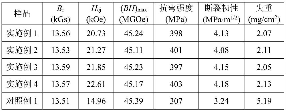
Embodiment 1

[0022] (1) The composition is Nd prepared by vacuum quick-setting process 29 Fe bal B 0.9 The main phase alloy A, the melting temperature is 1400°C, and the copper roll speed is 1m / s. The composition is Dy prepared by vacuum quick-setting process 40 Fe bal B 0.9 COL 0.01 The grain boundary phase alloy B, where L is a carbon nanotube, the diameter of the carbon nanotube is 1 nm, and the length is 1 μm. The melting temperature of the grain boundary phase alloy is 1300°C, and the rotational speed of the copper roll is 2m / s.

[0023] (2) The main phase alloy A and the grain boundary phase alloy B are respectively powdered by hydrogen crushing and jet milling, and the main phase alloy powder A1 with an average grain size of 2.0 μm and the grain boundary phase alloy powder of 0.5 μm are obtained B1.

[0024] (3) Fully mix the main phase alloy powder A1 and the grain boundary phase alloy powder B1 at a mass percentage ratio of 97.0:3.0 to obtain a mixed powder C.

[0025] (4...

Embodiment 2

[0027] (1) The composition is Nd prepared by vacuum quick-setting process 30 Fe bal B 1.0 The main phase alloy A, the melting temperature is 1430°C, and the copper roll speed is 1m / s. The composition is Dy prepared by vacuum quick-setting process 50 Fe bal B 1.0 Cu 2 L 0.5 The grain boundary phase alloy B, wherein L is a carbon nanotube, the diameter of the carbon nanotube is 10 nm, and the length is 10 μm. The melting temperature of the grain boundary phase alloy is 1320°C, and the rotational speed of the copper roll is 2m / s.

[0028] (2) The main phase alloy A and the grain boundary phase alloy B are respectively powdered by hydrogen crushing and jet milling, and the main phase alloy powder A1 with an average grain size of 3.0 μm and the grain boundary phase alloy powder of 1.0 μm are obtained B1.

[0029] (3) Fully mix the main phase alloy powder A1 and the grain boundary phase alloy powder B1 at a mass percentage of 99.9:0.1 to obtain a mixed powder C.

[0030] (...

Embodiment 3

[0032] (1) The composition is Nd prepared by vacuum quick-setting process 31 Fe bal B 1.0 The main phase alloy A, the melting temperature is 1450°C, and the copper roll speed is 1m / s. The composition is Tb prepared by vacuum quick-setting process 60 Fe bal B 1.0 Al 3 L 0.7 The grain boundary phase alloy B, wherein L is a carbon nanotube, the diameter of the carbon nanotube is 30nm, and the length is 15μm. The melting temperature of the grain boundary phase alloy is 1340°C, and the rotational speed of the copper roll is 2m / s.

[0033] (2) The main phase alloy A and the grain boundary phase alloy B are respectively powdered by hydrogen crushing and jet milling, and the main phase alloy powder A1 with an average grain size of 4.0 μm and the grain boundary phase alloy powder of 1.5 μm are obtained B1.

[0034](3) Fully mix the main phase alloy powder A1 and the grain boundary phase alloy powder B1 at a mass percentage of 98.5:1.5 to obtain a mixed powder C.

[0035] (4) ...


PUM

PropertyMeasurementUnit
diameteraaaaaaaaaa
lengthaaaaaaaaaa
magnetic flux densityaaaaaaaaaa

Abstract

The invention discloses a preparation method of a high-performance sintered neodymium-iron-boron magnet. The method comprises the following steps: respectively smelting a main phase alloy and a grainboundary phase alloy, respectively pulverizing, mixing, molding, carrying out grain boundary diffusion, sintering, and carrying out tempering heat treatment to finally obtain the sintered neodymium-iron-boron magnet. Heavy rare earth Dy or Tb, corrosion-resistant metals Co, Cu, Al and Zn and carbon nanotubes with excellent strength and flexibility are added during grain boundary phase alloy smelting, the added heavy rare earth Dy or Tb can improve the coercive force of the magnet, the added corrosion-resistant metals Co, Cu, Al and Zn can improve the potential of a grain boundary phase and reduce the chemical activity of the grain boundary phase, and the added high-melting-point carbon nanotubes do not change the nano form when the grain boundary phase is smelted, so that the mechanical property of the magnet is improved. Therefore, according to the sintered neodymium-iron-boron magnet prepared by the method, the corrosion resistance and the toughness of the magnet are remarkably improved on the basis of ensuring relatively high magnetic performance.

Description

technical field [0001] The invention belongs to the field of rare earth permanent magnet materials, and in particular relates to a high-performance sintered NdFeB magnet and a preparation method thereof. Background technique [0002] As an important basic magnetic functional material, permanent magnet materials have a wide range of applications, covering almost all industrial sectors, living areas, science and technology, aerospace and military, etc. Among them, sintered NdFeB magnets occupy "half of the country" of permanent magnet materials due to their excellent magnetic properties and higher cost performance, and are known as the contemporary "Magnetic King". The sintered NdFeB magnet prepared by powder metallurgy has a multi-phase structure, and the potential difference between the phases is relatively large, especially the electrochemical activity of the grain boundary phase is the highest, and it is easy to corrode in an electrochemical environment. As the anode, the...

Claims


Application Information

Patent Timeline
Patent Type & Authority Applications(China)
IPC IPC(8): H01F1/057H01F41/02
CPCH01F1/0577H01F41/0253H01F41/0293
Inventor 吴玉程曹玉杰崔接武徐光青刘晴张鹏杰孙威李炳山刘家琴
Owner HEFEI UNIV OF TECH
Why Eureka
Try Eureka