Ultra-low-nitrogen combustion equipment with post-premixing cold flame combustion coupling matrix tube mode wall structure

A technology of coupling matrix and combustion equipment, applied in the direction of burner, combustion method, combustion type, etc., can solve problems such as reducing user satisfaction, reducing equipment life, and increasing flue gas volume.

Active Publication Date: 2021-05-18
BEIJING BOOSTER BOILER
View PDF10 Cites 4 Cited by
  • Summary
  • Abstract
  • Description
  • Claims
  • Application Information

AI Technical Summary

Problems solved by technology

(4) Nitrogen oxides are also the main cause of acid rain and acid fog. NO and NO2 will form NO3- and H with moisture in the surrounding air +, leading to severe corrosion of metal surfaces
At present, there are three main technical routes for natural gas ultra-low nitrogen combustion: 1) flue gas circulation plus diffusion combustion; 2) metal fabric type premixed surface combustion; 3) porous media type premixed surface combustion; among them, the technical principle of flue gas circulation plus diffusion combustion It is to recover part (10-25%) of the flue gas after combustion and mix it with fresh air to reduce the oxygen concentration of the combustion-supporting air, thereby reducing the reaction intensity and reducing the temperature in the core area to achieve the purpose of low-nitrogen combustion. There are two problems with this technology: 1) After combustion, it passes through the furnace The flue gas volume increases, the blower load increases, the power consumption increases, the furnace back pressure increases, and the output decreases; 2) About 17% of the water vapor partial pressure in the return flue gas will inevitably condense to form condensed water after mixing with cold air, reducing Equipment life, reducing user satisfaction
The premixed surface combustion technology is to increase the combustion area by increasing the excess air coefficient, disperse the concentrated flame into many small flames, reduce the combustion temperature in the core area, and achieve low nitrogen. The disadvantage is that it needs to be equipped with a filter and needs to be replaced regularly. There is a risk of blockage in the process, and there are many technical risks of explosion and deflagration

Method used


Image

  • Ultra-low-nitrogen combustion equipment with post-premixing cold flame combustion coupling matrix tube mode wall structure

Examples


Embodiment Construction

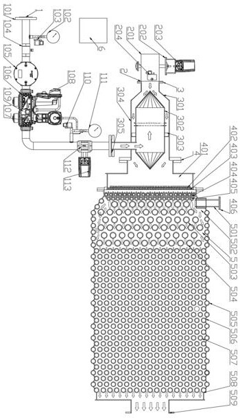
[0033] Combine below figure 1 , the present invention is further described:

[0034] Such as figure 1 As shown, the post-premixed cold flame combustion coupling matrix tube mode wall structure ultra-low nitrogen combustion equipment of the present invention includes a gas control device 1, an air volume control device 2, an air mixing device 3, a cold flame combustion device 4, a matrix tube and a mode wall device 5 and integrated controller 6.

[0035] Among them, the gas control device 1 includes an interface flange 101, a primary pressure gauge 102, a gas low pressure sensor 103, an emergency cut-off ball valve 104, a gas filter 105, a double valve body combination cut-off pressure regulating valve 106, and a cut-off pressure regulation actuator 107 , emergency cut-off actuator 108, gas leakage detection sensor 109, gas high pressure detection sensor 110, secondary gas pressure direct reading pressure gauge 111, gas flow regulating valve 112 and gas flow regulating actuat...


PUM


Abstract

The invention relates to ultra-low-nitrogen combustion equipment with a post-premixing cold flame combustion coupling matrix tube mode wall structure. The ultra-low-nitrogen combustion equipment comprises a fuel gas regulation and control device, an air volume regulation and control device, an air-gas mixing device, a cold flame combustion device, a matrix tube and mode wall device and a comprehensive controller. The fuel gas regulation and control device provides fuel gas for the air-gas mixing device; the air volume regulation and control device provides combustion-supporting air for the air-gas mixing device; the air-gas mixing device conducts jet flow mixing on combustible gas provided by the fuel gas regulation and control device and the combustion-supporting air provided by the air volume regulation and control device, and the combustible gas and the combustion-supporting air are evenly mixed through the air-gas mixing device and then injected into the cold flame combustion device; the mixed gas sequentially passes through a double-layer rectifying plate, a hexagonal heat pipe type cooling fire-retardant tube nest and a flame cooling tube nest in the cold flame combustion device and then enters a combustion chamber for combustion; and after combustion, high-temperature flue gas is subjected to radiation and convective heat exchange in the combustion chamber, then exchanges heat with a medium in the matrix tube and mode wall device and then is discharged into a flue.

Description

technical field [0001] The invention relates to the technical field of clean energy, in particular to a post-premixed cold flame combustion coupling matrix tube mode wall structure ultra-low nitrogen combustion equipment to realize the application of natural gas energy with low power consumption, high energy efficiency and ultra-low nitrogen emission. Background technique [0002] With the development of my country's economy and society, the original energy development model can no longer meet the needs of social development, and the energy utilization form of energy conservation and environmental protection is the current development direction. The national long-term energy development strategy plans to reduce the proportion of coal in primary energy consumption to below 50% by 2030. Data show that from 2006 to 2015, the proportion of global coal and oil consumption decreased by about 2.3 percentage points, while the proportion of natural gas increased by about 1 percentage...

Claims


Application Information

Patent Timeline
Patent Type & Authority Applications(China)
IPC IPC(8): F23D14/02F23D14/46F23D14/62F23D14/68F23D14/70F23D14/82
CPCF23D14/02F23D14/46F23D14/62F23D14/68F23D14/70F23D14/82F23D2203/007
Inventor 吴同杰代文娟刘鹤吴庆福刘忠赫李炳希赵冀哲郭红召王冲金艺花
Owner BEIJING BOOSTER BOILER
Why Eureka
Try Eureka