Photocatalyst material and process for producing the same

A technology of photocatalyst and manufacturing method, which is applied in the direction of catalyst activation/preparation, chemical instruments and methods, physical/chemical process catalysts, etc. It can solve the problems of cost problems such as the insertion of the bottom layer of the substrate, and achieve high photocatalytic activity. Effect

Inactive Publication Date: 2005-10-12
安地斯科技有限公司
View PDF9 Cites 3 Cited by
  • Summary
  • Abstract
  • Description
  • Claims
  • Application Information

AI Technical Summary

Problems solved by technology

These technologies are to form a silicon oxide film porously, or perform microfabrication on a titanium oxide film and a glass substrate, and provide unevenness on the surface to increase the area of ​​the exposed surface of the photocatalyst, thereby improving the photocatalytic function. but not necessarily a significant improvement
In addition, there are also problems in the cost of substrate processing, film processing, and insertion of the bottom layer.

Method used


Image

  • Photocatalyst material and process for producing the same
  • Photocatalyst material and process for producing the same
  • Photocatalyst material and process for producing the same

Examples


Embodiment 1

[0105]

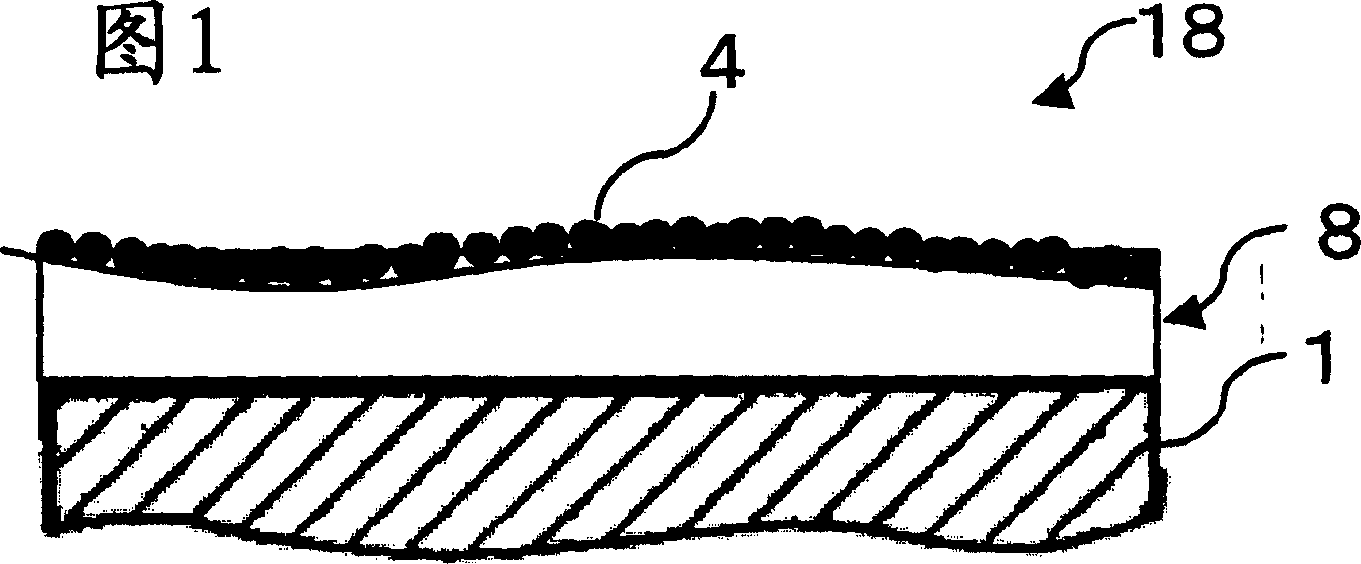
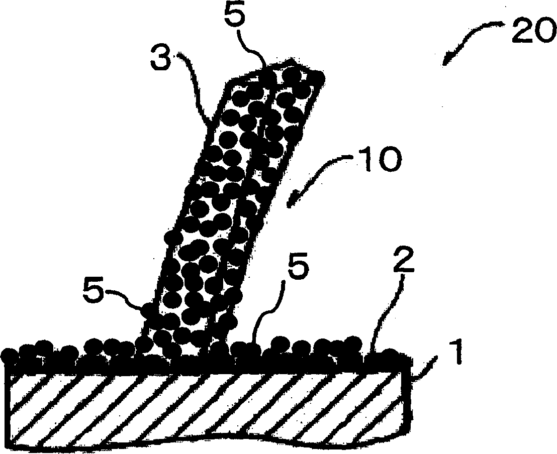
[0106] The columnar hollow titanium oxide photocatalyst material was loaded with Cu by the above-mentioned photoprecipitation method to fabricate a titanium oxide filter. It was confirmed by SEM observation of the obtained photocatalyst material that Cu microparticles with a particle diameter of 1 to 50 nm were supported on the surface of the titanium oxide crystal.

Embodiment 2

[0107]

[0108] Copper sulfate trihydrate (Cu(NO 3 )2 ·3H 2 O Wako Pure Chemicals special grade), the concentration was adjusted to 2 × 10 -5 mol / L, impregnate the titanium oxide filter in the copper nitrate aqueous solution and let it stand for 24 hours. Through this operation, Cu is adsorbed on the titanium oxide surface until equilibrium adsorption is reached. After supporting Cu on the titania filter, it was washed with pure water. Thereafter, it was dried at 150° C. for 1 hour, and heat-treated at 450° C. in air for 2 hours. In the state of heat treatment in air, the Cu surface is in an oxidized state, so it is reduced in a hydrogen atmosphere. A titania filter was filled in the quartz glass tube, and reduction treatment was performed at 450° C. in a 10 vol % hydrogen-argon mixed gas for 2 hours. In the photocatalyst material thus obtained, it was confirmed by SEM observation that Cu microparticles having a particle diameter of 1 to 50 nm were supported on the surf...

Embodiment 3

[0109]

[0110] It carried out by the sputtering method using the RF magnetron sputtering apparatus (Nippon Vacuum Technology Co., Ltd., SH-350EL-T06). In the film-forming chamber, the substrate carrying the titanium oxide photocatalyst of the columnar hollow structure and the Cu target were placed facing each other. As the target, Cu palladium with a target purity of 99.99% or higher was used. Use an oil rotary pump to pump air to 10Pa. Thereafter, air is pumped by a turbomolecular pump to bring the film-forming chamber to a predetermined degree of vacuum. Next, argon gas with a purity of 99.999% or more is introduced to make the film forming chamber an argon atmosphere. At this time, the flow rate of the introduced gas and the opening / closing degree of the main valve are adjusted so that the predetermined argon gas pressure (sputtering pressure) is reached. Then, the Cu target was externally energized by a DC power supply to perform Cu sputtering, and the set titanium o...


PUM

PropertyMeasurementUnit
particle diameteraaaaaaaaaa

Abstract

A process for producing a photocatalyst material, the photocatalyst material exhibiting highly active photocatalytic action and capable of reducing special odor generated at the time of ultraviolet irradiation. This process comprises the raw photocatalyst material preparation step (P1) of obtaining a photocatalyst material (raw photocatalyst material) being in the state of not bearing any base metal on its surface and the base metal superimposition step (P3) of causing the raw photocatalyst material obtained in the step P1 to bear base metal fine particles on its surface to thereby obtain the photocatalyst material bearing a base metal. The base metal superimposition step P3 comprises the solution treatment step (P31) of dipping the raw photocatalyst material in a base metal compound solution according to photoprecipitation, the ultraviolet irradiation step (P32) of irradiating the base metal bearing photocatalyst material obtained in the step P31 with ultraviolet light and the drying step (P33) of drying the photocatalyst material resulting from the step P 32.

Description

technical field [0001] The present invention relates to a photocatalyst material and a manufacturing method thereof, in particular to an oxide photocatalyst material capable of exhibiting a highly active photocatalytic function at low cost and capable of alleviating peculiar odors generated when ultraviolet rays are irradiated, and a manufacturing method thereof. Background technique [0002] When an oxide photocatalyst represented by titanium oxide is irradiated with light having a wavelength of energy above its band gap, electrons are generated in the conduction band and holes are generated in the valence band due to photoexcitation, and by their strong reducing power or oxidation It can decompose organic matter or nitrogen oxides in contact with the photocatalyst into water and carbon dioxide, etc., and has antifouling, deodorizing, and antibacterial functions. Various environmental purification methods and devices using this function have been provided, but in order to f...

Claims


Application Information

Patent Timeline
Patent Type & Authority Applications(China)
IPC IPC(8): B01J23/72B01J19/08B01J19/12B01J21/06B01J35/00B01J35/02B01J37/02B01J37/34C03C17/00C03C17/23C03C17/245C03C17/25C23C14/06C23C16/30
CPCB01J37/0238C03C17/23C03C2217/71C03C17/2456B01J21/063B01J37/345C03C2217/42C03C17/256C03C17/007B01J35/004B01J35/02B01J21/06
Inventor 中村友宇子工藤武志类家东川浪文江苗代泽教夫岩崎佑司葛堀健手仓森聪
Owner 安地斯科技有限公司
Why Eureka
Try Eureka