China channel oil maker and system by drying and pyrolyzing biomass materials containing straw

A biomass, chain-channel technology, applied in the fields of renewable resources and environmental protection, energy and chemical industry, can solve the problems of difficult random adjustment of process parameters, long residence time, and complex process.

Inactive Publication Date: 2007-04-04
张民良
View PDF4 Cites 0 Cited by
  • Summary
  • Abstract
  • Description
  • Claims
  • Application Information

AI Technical Summary

Problems solved by technology

[0003] 1. The condensable liquefied oil gas produced by the fluidized bed reactor stays in the high temperature area for a long time, and the secondary reaction is serious, which reduces the collection rate and oil quality;
[0004] 2. The particle residence time is short, the pyrolysis is insufficient, and the conversion rate of volatile components is low; it is difficult to start and stop the system, and a large number of additional conditions and auxiliary materials are required;
[0005] 3. It is difficult to adjust the process parameters randomly, and the fluctuation of the operating state parameters has a severe reaction to the product quality and recovery rate, which cannot adapt to the scale-up of the industry, and cannot automatically adapt to the changes in the quality of raw materials and physical parameters;
[0006] 4. For raw materials with high moisture content, it is necessary to mix (reverse mix) the dried raw materials at the inlet to enter the drying or incineration or pyrolysis reactor, and the process is complicated;
[0007] 5. When the raw material enters the drying or pyrolysis reactor, it cannot directly use the high-temperature high-energy fluid generated by the heat generation subsystem to avoid over-burning and fouling of the sludge, and even the possibility of deflagration or explosion , which seriously affects the thermal energy utilization efficiency
The organic matter in the sludge is about 50%, and the calorific value of the dry mixed sludge is 24-29MJ / kg. Theoretically, the calorific value held by itself can only be burned when the water content is lower than 70%. Moisture is a better fuel and can generate abundant heat; however, the existing sludge drying or incineration equipment such as rotary kiln, rotary furnace, fluidized bed, etc., due to the high moisture content, high viscosity and solidification of sludge The characteristics of serious scale, low efficiency of equipment, bulky, complex process, high investment, and need to dehydrate a large amount of water to be used as raw materials for treatment, and the sludge dust that is inevitably generated during the drying process is easy to explode, we have not yet See the report on the industrial scale technical equipment of the present invention using straw biomass pyrolysis to produce liquefied oil

Method used


Image

  • China channel oil maker and system by drying and pyrolyzing biomass materials containing straw
  • China channel oil maker and system by drying and pyrolyzing biomass materials containing straw
  • China channel oil maker and system by drying and pyrolyzing biomass materials containing straw

Examples


Embodiment 3

[0078] In Figures 5 and 7, an embodiment 3 of the present invention used as a dryer is shown;

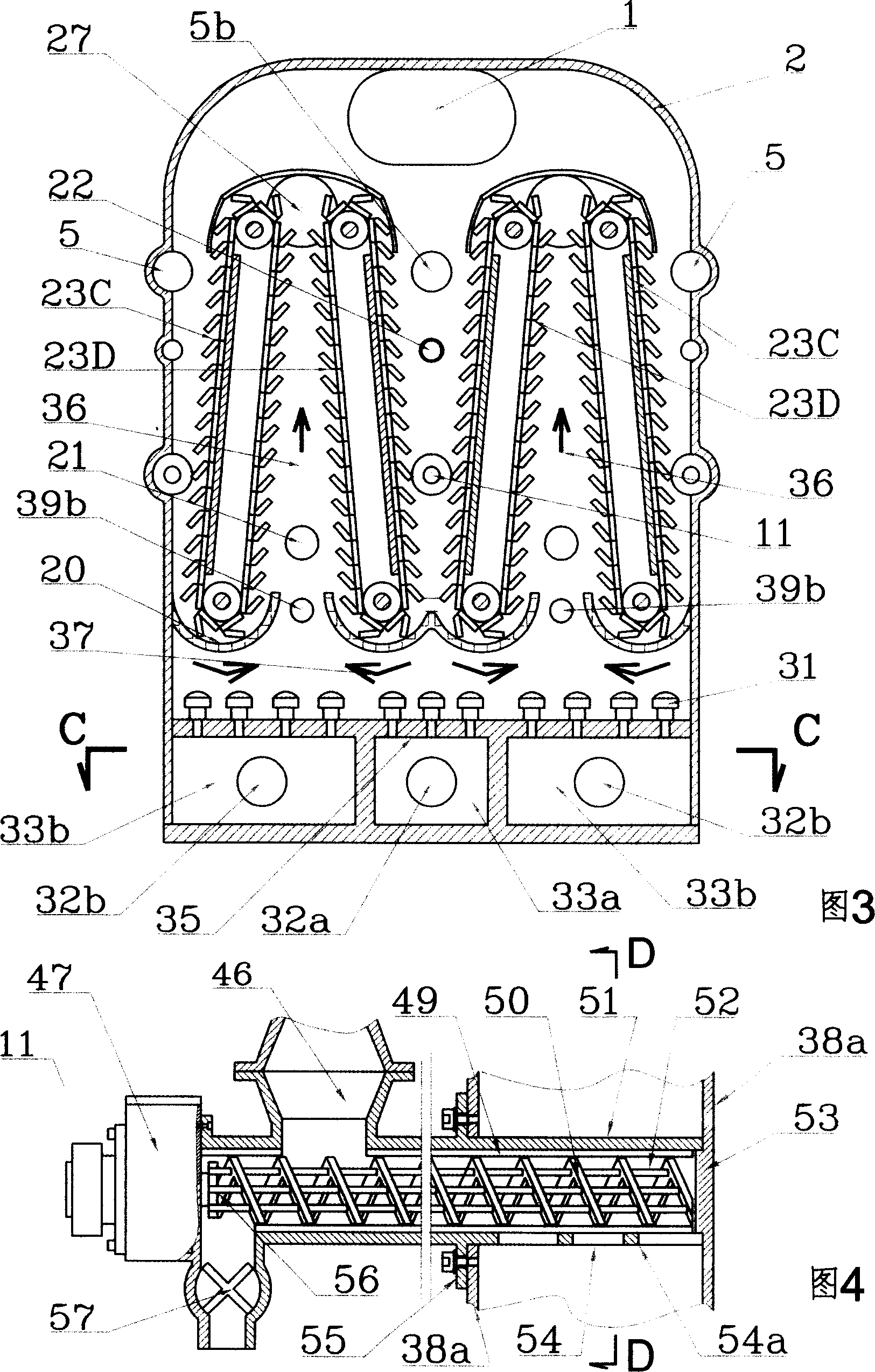
[0079] The feature of this embodiment is that two groups of chain heat exchangers are formed into a pair of symmetrically inclined chain heat exchangers 23A and 23B, and two pairs of chain heat exchangers 23C, 23D and 23E are arranged in the housing 2, and two of them A heating passage 38 is arranged between the adjacent downlinks of the chain heat exchanger, and a burner 39 of fluid fuel is arranged on the top wall of the heating passage 38, and the flame injection position of the burner 39 is heated on the downlink side. Plate 38a, the high-temperature gas 37 passes through the turning chain 15 at the lower end of the uplink, and then turns from the top of the constant temperature space through the downlink to enter the channel between the heating wall plate 38a and the vertical wall of the housing, and from the waste gas discharge port at the bottom of the channel 1a is discharge...

Embodiment 5

[0082] In Figures 9, 14 and 15, the present invention is shown as an embodiment 5 in which drying is the main method and pyrolysis is the auxiliary method;

[0083] Among the three groups of chain heat exchangers set in the constant temperature space, two groups of chain heat exchangers 23A, 23B form a pair of symmetrically inclined chain heat exchangers, and the downlink of the pair of chain heat exchangers 23B The chain cables of the chain path are adjacent to the uplink path of another group of chain path heat exchangers 23E, and the chain paths of the chain path heat exchangers 23E are arranged in the chain path formed by their own chain cable partition screen 8 and the heating vertical wall 38a In 40, each chain cable of each group of chain heat exchangers moves in parallel through the uplink, downlink, and the steering chain formed by the driving sprocket and the driven sprocket and then closed. A burner 39 of fluid fuel is arranged on the top wall of the heating channel...

Embodiment 6

[0086] In Figure 10, the present invention is shown as an embodiment 6 in which drying is the main method and pyrolysis is the auxiliary method;

[0087] The feature of this embodiment is that two sets of chain heat exchangers are formed into a pair of symmetrically inclined chain heat exchangers 23A and 23B, and three pairs of chain heat exchangers 23A, 23B and 23E are arranged in the housing 2, two of which A heating passage 38 is arranged between the adjacent downlinks of the group chain heat exchangers 23B and 23E, and a burner 39 of fluid fuel is arranged on the top wall of the heating passage 38, and the flame injection position of the burner 39 is in the downlink. The so-called heating wall plate 38a is heated by the side, and the high-temperature gas 37 passes through the uplink of the chain heat exchanger 23E, the turning chain 15 at the lower end, and then passes through the uplink of the chain heat exchanger 23B and 23A from the bypass exhaust port 27 is connected t...


PUM


Abstract

Biomass chain oil maker with drying and pyrolyzing functions and its system are disclosed. It consists of heat generating system, constant-temperature space, electromechanical integrated equipment of biomass oil purifying system and controlling system, heat generating system comprises heating furnace, feeding system, at least a chain heat exchanger, air pre-heater and tailed gas treater, temperature in constant-temperature space is kept between 80-900 degree, constant-temperature space is closed case set with thermal-insulating layer periphery, each set of chain heat exchanger consists of at least one chain rope, driver, heat-transferring wall, driving chain wheel and driven chain wheel; ascending chain and descending chain get through by each chain rope, steering chain containing driving chain wheel and driven chain wheel are closed. Raw material with high-water content passes by ascending chain and descending chain as water-content evaporating section, and pyrolyzed gas evaporating section and high-temperature section. The process is carried out by evaporating, pyrolyzing, crushing for mud carbon, drying and burning. It can be used to manufacture inflammable gas, mud carbon and liquid fuel.

Description

technical field [0001] The invention relates to a biomass chain drying and pyrolysis oil production device and system for highly water-containing viscous and fine-grained substances including straw, belonging to the fields of energy chemical industry, renewable resources and environmental protection; the device is especially suitable for sludge Disposal, river dredging mud treatment, drilling mud treatment, coal washing slime treatment, biomass liquefaction and livestock and poultry breeding industry pollutants disposal and other projects. Background technique [0002] In the known technology of obtaining biomass liquefied oil after biomass pyrolysis, cracking reactors such as fluidized bed, circulating fluidized bed and rotating cone are generally used. For example, biomass integrated pyrolysis graded preparation of liquid fuel device (CN1390915), the method for preparing bio-oil from biomass hydrolysis residue (CN1385508), its technology all uses flui...

Claims


Application Information

Patent Timeline
Patent Type & Authority Applications(China)
IPC IPC(8): C10G1/00
Inventor 张民良
Owner 张民良
Why Eureka
Try Eureka