Bioreactor-direct microbe fuel cell and use thereof

A bioreactor and fuel cell technology, applied in biochemical fuel cells, fuel cells, electrochemical generators, etc., can solve the problem of single raw material and low efficiency, and achieve the effects of good stability, clean power generation, and wide source of raw materials

Inactive Publication Date: 2007-04-18
INST OF PROCESS ENG CHINESE ACAD OF SCI
View PDF1 Cites 40 Cited by
  • Summary
  • Abstract
  • Description
  • Claims
  • Application Information

AI Technical Summary

Problems solved by technology

[0005] Another object of the present invention is to provide the application of bioreactor-direct microbial fuel cell, to overcome the defect of single low efficiency of the raw material of existing microbial fuel cell, to de

Method used


Image

  • Bioreactor-direct microbe fuel cell and use thereof
  • Bioreactor-direct microbe fuel cell and use thereof
  • Bioreactor-direct microbe fuel cell and use thereof

Examples


Embodiment 1

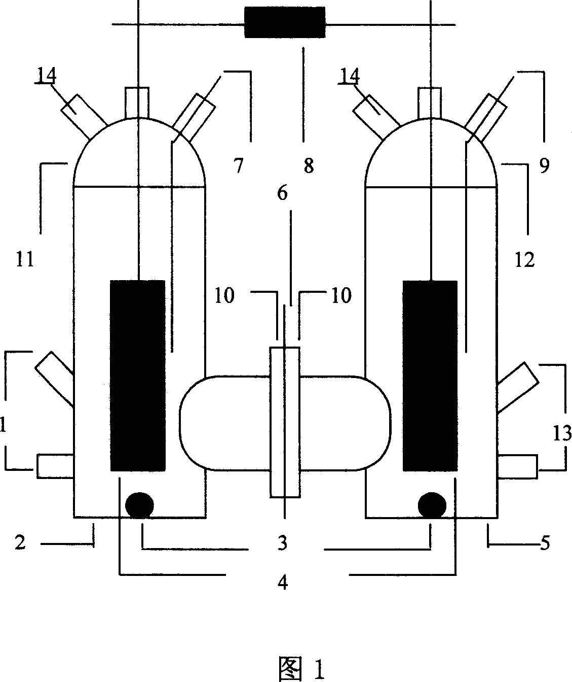
[0042] See Figure 1. The bioreactor-direct microbial fuel cell mainly includes an anode chamber 2, a cathode chamber 5, a polytetrafluoroethylene flange (with a groove and a gasket) 10 separating the two chambers, and a proton exchange is fixed between the two flanges. Membrane 6, the main components of the anolyte (200mL) in the anode chamber 2 are: 0.6g sodium chloride, 0.12g sodium dihydrogen phosphate, 0.5g sodium bicarbonate, pH 6.8-7.0. The anode chamber has an interface 1 for inoculation, sample addition and sampling analysis, and a cover 11 connected to the grinding port on the upper end. The graphite rod 4 is fixed on the cover, and there is a sterile N 2 -CO 2 (Volume ratio 80:20) mixed gas inlet 7, mixed gas enters the anolyte through the latex tube sealed with raw material tape through the injection needle shaped inlet pipe installed at the inlet. The main components of catholyte (200 mL) in cathode chamber 5 are: 0.6 g sodium chloride, 0.12 g sodium dihydrogen p...

Embodiment 2

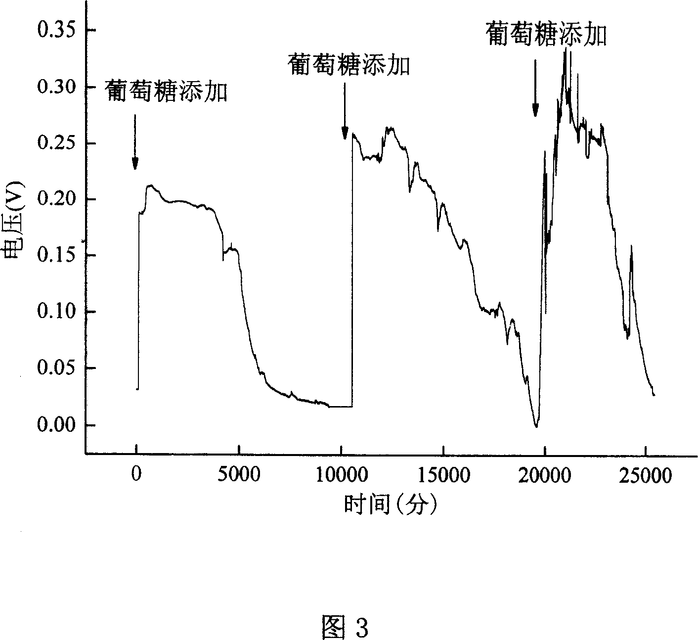
[0044] Utilizing the bioreactor and reaction conditions of Example 1, wherein the diameter of the magnetic stirring bar used is 1.5 cm, 0.36 g of glucose was added into the anode chamber 2, and R. ferrireducens was inoculated with a syringe at 10%. After a period of growth, under the condition of an external resistance of 500Ω and without adding any catalyst to the cathode, the voltage between the two electrode chambers can reach 0.25V, and the current density can reach 80mA / m 2 , the voltage can last for about 15 days. After the voltage drops to the baseline voltage, that is, when the glucose is exhausted, add 0.036g of glucose (fuel) in time, and the voltage can quickly return to the original level for about 3 days, as shown in Figure 3 .

Embodiment 3

[0046] As in the reactor and reaction conditions of Example 2, after the battery is operating normally, when the glucose is exhausted, that is, when the voltage drops to the baseline voltage, inject 5ml of monosodium glutamate wastewater, the initial COD is 1500mg / L, and the voltage will quickly rise to about 0.2V , the voltage can last for about 7 days, and after 7 days of reaction, the COD of the wastewater is reduced to 200mg / L, as shown in Figure 4.


PUM

PropertyMeasurementUnit
Diameteraaaaaaaaaa
Diameteraaaaaaaaaa

Abstract

The invention belongs to bioenergy source utilizing field, especially relating to a bioreactor-direct microbial fuel cell and its use. And it mainly comprises tubular anode chamber and cathode chamber and proton exchange membrane to isolate the two chambers, where both the electrodes are of unpolished high-purity graphite rod; the anode is inoculated with bacteria, where before inoculation, charging aseptic N2-CO2(80:20) mixed gas to remove all oxygen gas from culture medium and after inoculation, slowly charging mixed gas and keeping strict anaerobic environment; the cathode keeps charging aseptic air and keeps dissolved oxygen concentration in the aseptic air; in the two chambers, slowly blending with magnetic blender; before used, the battery device is processed by high pressure moisture-heat sterilization. And the invention can use glucose, fructose, xylose, sucrose, maltose, and other sugar-containing matters and organic waste water as raw materials and directly converts their chemical energies into electric energy, having characters of no medium toxicity, good stability, moderate operating conditions, clean power generation, etc.

Description

technical field [0001] The invention belongs to the field of bioenergy utilization, in particular to a bioreactor-direct microbial fuel cell and its application. Background technique [0002] At present, the utilization of bioenergy is mostly through microbial fermentation to generate fuel ethanol, or biodiesel, and biohydrogen production. However, there will be problems such as technical difficulties and high costs, which will affect the effective use of bioenergy. As a bioreactor, microbial fuel cells can quantitatively and effectively convert chemical energy in biomass into electrical energy, and can use organic wastewater as fuel to obtain electrical energy while treating wastewater. [0003] For example, the "microbial fuel cell" disclosed by the patent publication No. CN1588683 is mainly composed of an anode and a cathode cavity, separated by a partition in the middle, and there are holes on the partition, and hydrogen ion selection is arranged on the hole. membrane,...

Claims


Application Information

Patent Timeline
IPC IPC(8): H01M8/16H01M8/06
CPCY02E60/527Y02E60/50
Inventor 刘志丹李浩然杜竹玮李绍华祝学远
Owner INST OF PROCESS ENG CHINESE ACAD OF SCI
Why Eureka
Try Eureka