Method for producing a planar polymer stack

a polymer and stack technology, applied in the field of polymer stacks, can solve the problems of inability to use the intended application, inability to control the so-called “upper” interface of the system, and inability to stabilize or even stabilize the entire system

Active Publication Date: 2022-09-27
ARKEMA FRANCE SA
View PDF7 Cites 0 Cited by
  • Summary
  • Abstract
  • Description
  • Claims
  • Application Information

AI Technical Summary

Problems solved by technology

In these systems of stacks of layer(s) of polymer materials, in which the configurations may be, for example, “liquid/solid” or “liquid/liquid”, the surface energies of the various layers may be very different, thus making the entire system metastable or even unstable due to the mathematical formulation of the spreading parameter S.
Irrespective of the mechanisms (spinodal decomposition or nucleation/growth), this type of liquid/liquid system has a tendency to be particularly unstable and leads to the introduction of severe defects in the form of a discontinuity of the film under consideration, i.e. in the example of FIG. 10 the first polymer layer 20, the initial planarity of which is thereby disrupted, with the appearance, in the best of cases, of holes in the film or the double-layer of polymer films, thus making it unusable for the intended applications.
On the other hand, the control of the so-called “upper” interface of the system, i.e. the interface between the block copolymer and the surrounding atmosphere, remains markedly less well controlled at the present time.
Indeed, on account of hydrodynamic phenomena leading to the amplification of capillary waves of the top coat TC layer and of its interaction with the underlying layer of block copolymer BCP, this type of stack has a tendency to be particularly unstable and leads to the introduction of severe defects in the form of a discontinuity in the block copolymer BCP film, thus making it unsuitable for use, for example, as a nanolithography mask for electronics.
Moreover, the thinner the deposited polymer film, that is to say at least once the gyration radius of a molecular chain of the polymer under consideration, the more unstable or metastable it will tend to b

Method used


Image

  • Method for producing a planar polymer stack
  • Method for producing a planar polymer stack
  • Method for producing a planar polymer stack

Examples


example 1

olymers Used

[0211]The poly(1,1 dimethylsilacyclobutane)-block-polystyrene (“PDMSB-b-PS”) block copolymers used were synthesized by sequential anionic polymerization, as already reported in the prior art (K. Aissou &al., Small, 2017, 13, 1603777). The block copolymer No. 1 more specifically used here has a number average molar mass (Mn) of 17,000 g / mol, with a polydispersity index of 1.09 measured by steric exclusion chromatography (SEC) with polystyrene standards. The characterization shows a composition of 51% (by mass) PS and 49% (by mass) PDMSB. The block copolymer No. 2 more specifically used here has a number average molar mass (Mn) of 14,000 g / mol, with a polydispersity index of 1.07. The characterization shows a composition of 51% (by mass) PS and 49% PDMSB. The period of the block copolymer No. 1 is measured at ˜18 nm, that of No. 2 is measured at ˜14 nm, via a fast Fourier transform (FFT) of images taken by scanning electron microscopy (SEM), on self-organized films. As des...

example 2

of Surface Passivation Layers and Top Coat Layers

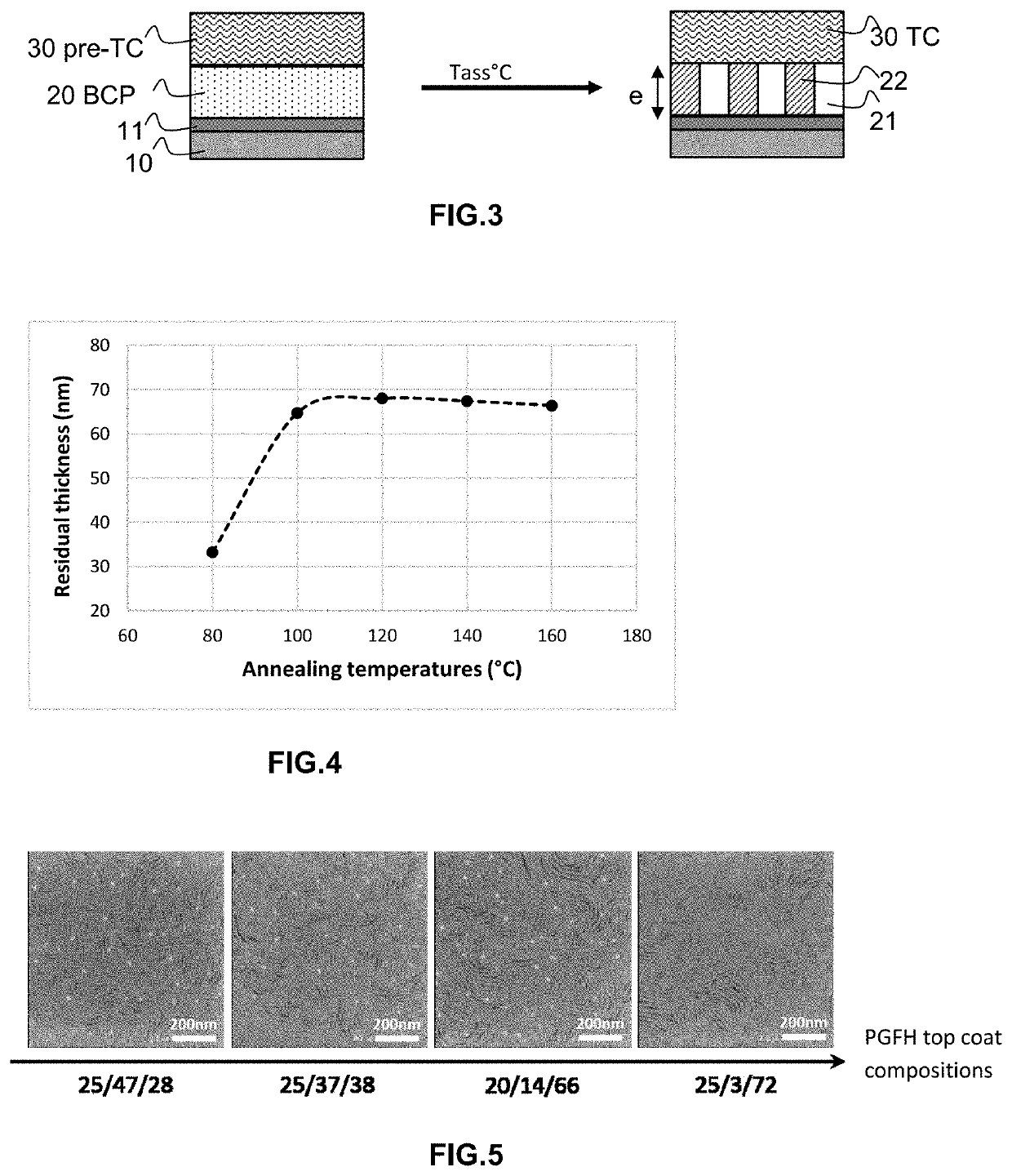
[0212]The copolymers or homopolymers used in the context of the invention have been synthesized by standard methods such as NMP (nitroxide mediated polymerization, for example with an initiator such as Arkema's initiator marketed under the name BlocBuilder®) or a conventional radical method (with an initiator such as azobisisobutyronitrile), known to the one skilled in the art. The number average molar mass obtained are typically of the order of Mn-5,000-10,000 g / mol. The polymer used as a neutralizing underlayer is a 2-ethylhexyl polymethacrylate homopolymer. The copolymer used as a top coat layer has a copolymer architecture of the poly(glycidyl methacrylate-co-trifluoroethyl methacrylate-co-hydroxyethyl methacrylate) type, subsequently abbreviated to “PGFH”, of variable “GFH” compositions, ranging from 25 / 3 / 72 to 25 / 47 / 28, by mass compositions. In the absence of other specifications explicitly mentioned, the results obtained being ...

example 3

for Top Coat Copolymers

[0213]The various copolymers synthesized according to Example 2 of the PGFH type are all soluble entirely in alcoholic solvents up to 10% by weight or less, such as methanol, ethanol, isopropanol, PGME (propylene glycol methyl ether), or ethyl lactate, as well as in mixtures of these same solvents in any proportions. The block copolymers described in Example No. 1 are not soluble in the same solvents or mixtures thereof.

[0214]Solubility parameters for these different solvents are available in the literature (Hansen, Charles (2007). Hansen Solubility Parameters: A user's handbook, Second Edition. Boca Raton, Fl.: CRC Press. ISBN 978-0-8493-7248-3.), but they are grouped in Table 1 below for convenience:

[0215]

TABLE 1Hansen parameters at 25° C. ((MPa)1 / 2)SolventCAS No.δDδPδHmethanol67-56-115.112.322.3ethanol64-17-515.88.819.4PGME107-98-215.66.311.6isopropanol67-63-015.86.116.4ethyl lactate687-47-8167.612.5

[0216]When these solvents are used to solubilize PGFH copo...


PUM

PropertyMeasurementUnit
Temperatureaaaaaaaaaa
Fractionaaaaaaaaaa

Abstract

The invention relates to a method for manufacturing a flat polymeric stack, said stack comprising one or more first and one second layer of (co)polymer (20, 30) stacked one on the other, the first underlying (co)polymer layer (20) not having undergone any prior treatment allowing its crosslinking, at least one of the (co)polymer layers initially being in a liquid or viscous state, said method being characterized in that the upper layer (30), known as the top coat (TC), is deposited on the first layer (20) in the form of a prepolymer composition (pre-TC), comprising one or more monomer(s) and/or dimer(s) and/or oligomer(s) and/or polymer(s) in solution, and in that it is then subjected to a heat treatment capable of causing a crosslinking reaction of the molecular chains within said layer (30, TC).

Description

[0001]This application is a 371 of PCT / FR2018 / 052964, filed Nov. 23, 2018.FIELD OF THE INVENTION[0002]The present invention relates to the field of polymeric stacks.[0003]More particularly, the invention relates to a method for controlling the planarity of such stacks. The invention further relates to a method for manufacturing a nanolithography mask using such a stack, the planarity of which is controlled, and a polymeric stack obtained via said planarity control method.[0004]Polymer stacks are used in a multitude of industrial applications, among which mention may be made, in a non-exhaustive manner, of the production of coatings for the aerospace or aeronautical or motor vehicle or wind turbine sector, inks, paints, membranes, biocompatible implants, packaging materials, or optical components, for instance optical filters, or microelectronic, or optoelectronic, or microfluidic components. The invention applies to all the applications, whatever they are, provided that the stack co...

Claims


Application Information

Patent Timeline
IPC IPC(8): G03F1/48C08F287/00G03F1/80
CPCG03F1/48C08F287/00G03F1/80G03F7/0002G03F7/0045G03F7/027G03F7/038G03F7/091G03F7/095G03F7/0955G03F7/11G03F7/2059G03F7/028G03F7/033G03F7/0757G03F7/422
Inventor CHEVALIER, XAVIER
Owner ARKEMA FRANCE SA
Why Eureka
Try Eureka