Systems and processes for providing hydrogen to fuel cells

Inactive Publication Date: 2002-07-25
AIR PROD & CHEM INC
View PDF91 Cites 113 Cited by
  • Summary
  • Abstract
  • Description
  • Claims
  • Application Information

AI Technical Summary

Benefits of technology

0014] The disclosed fuel-cell-based electrical generation systems and processes address the deficiencies of the prior art fuel cell electrical generation systems. This is particularly true for purification of reformate hydrogen, energy-efficient PSA oxygen enrichment, heat recovery from the fu

Problems solved by technology

External production, purification, dispensing and storage of hydrogen (either as compressed gas or cryogenic liquid) requires costly infrastructure, while storing of hydrogen fuel on vehicles presents considerable technical and economic barriers.
However, the resulting hydrogen contains contaminants, such as carbon monoxide and carbon dioxide impurities, that cannot be tolerated respectively by the PEM fuel cell catalytic electrodes in more than trace levels.
The conventional method of removing residual carbon monoxide from the hydrogen feed to PEM fuel cells has been catalytic selective oxidation, which compromises efficiency as both the carbon monoxide and a fraction of the hydrogen are consumed by low temperature oxidation, without any recovery of the heat of combustion.
Palladium diffusion membranes can be used for hydrogen purification, but have the disadvantages of delivering purified hydrogen at low pressure, and also the use of rare and costly materials.
This system is cumbersome and expensive to implement due to the large size of the adsorbers and the complexity of the valving required.
Further, the conventional PSA system use of applied energy inefficiently because of irreversible gas expansion steps as adsorbers are cyclically pressurized and depressurized within the PSA process.
Conventional PSA systems could not be applied to fuel cell power plants for vehicles, as such PSA systems are far too bulky and heavy because of their low cycle frequency and consequently large

Method used


Image

  • Systems and processes for providing hydrogen to fuel cells
  • Systems and processes for providing hydrogen to fuel cells
  • Systems and processes for providing hydrogen to fuel cells

Examples


Embodiment Construction
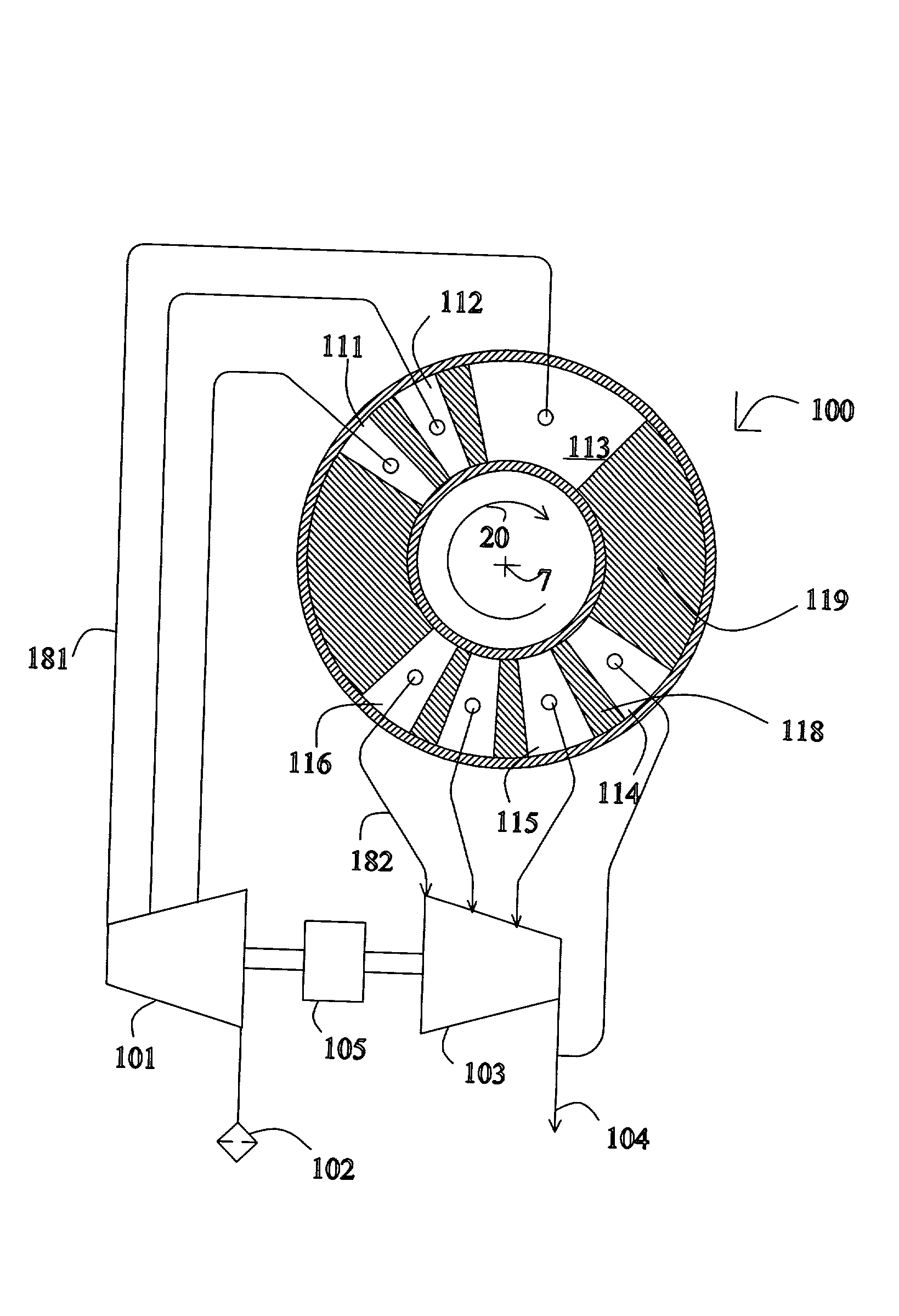
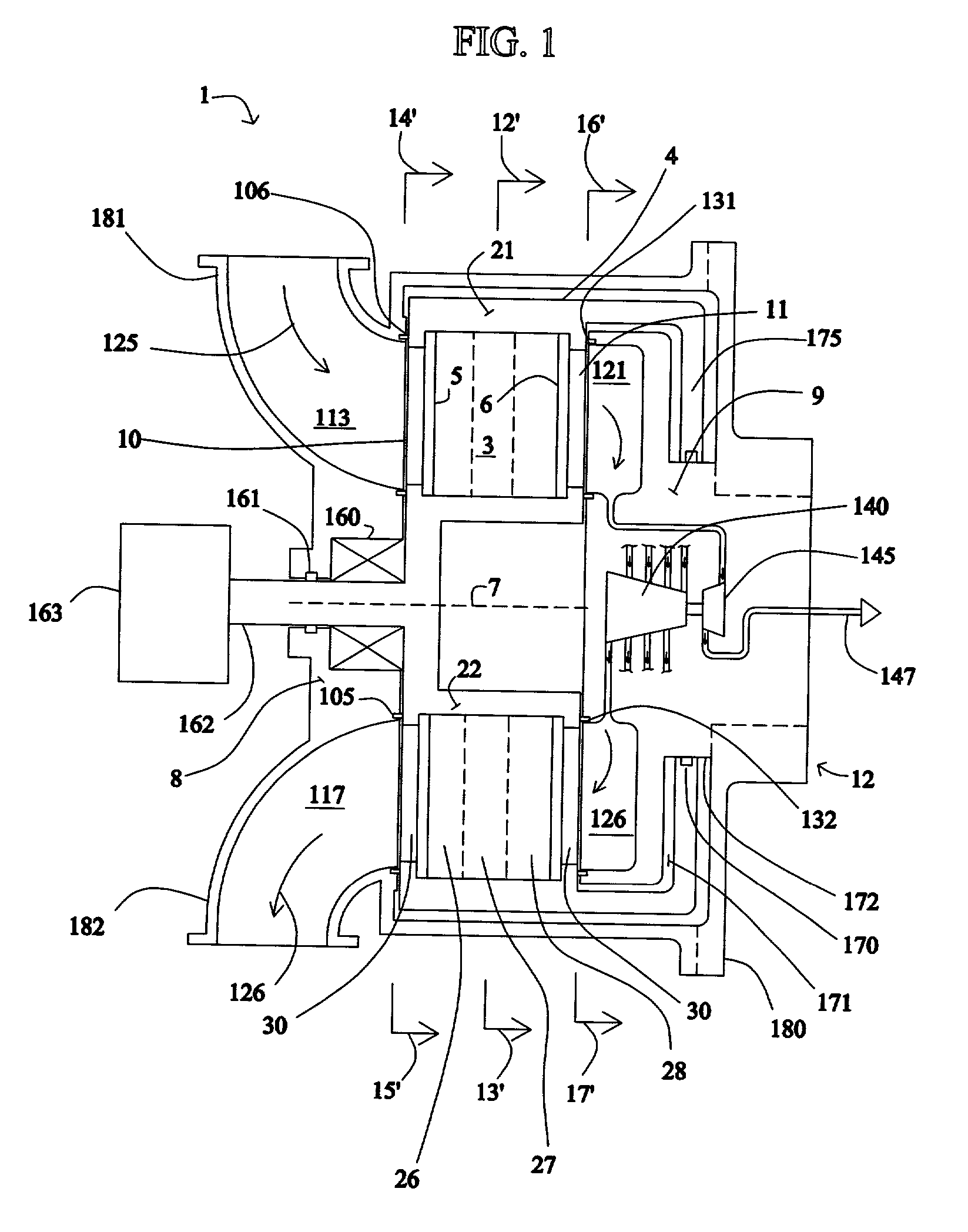
[0061] FIGS. 1-5

[0062] One embodiment of an oxygen-enrichment rotary PSA module for use with the described methods and systems is described below in connection with FIGS. 1-5B, but the same or similar rotary PSA module configuration could be used for hydrogen enrichment (i.e., separation) in the disclosed electrical current generating systems. As used herein, a "rotary PSA" includes, but is not limited to, either a PSA wherein the adsorbent bed rotates relative to a fixed valve face or stator or a PSA wherein the valve face or stator rotates relative to a fixed adsorbent bed.

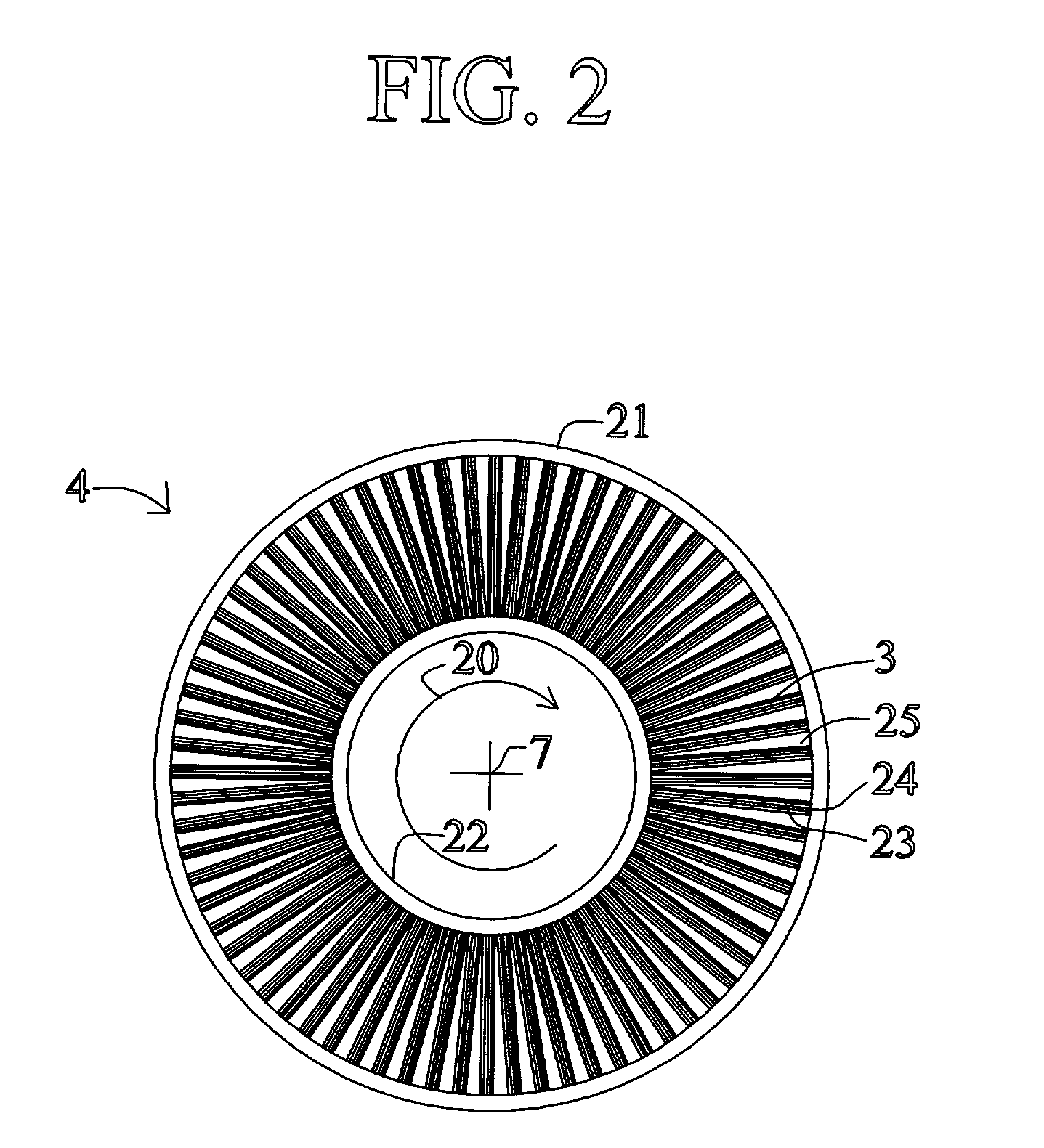
[0063] FIG. 1 shows a rotary PSA module 1, which includes a number "N" of adsorbers 3 in adsorber housing body 4. Each adsorber has a first end 5 and a second end 6, with a flow path therebetween contacting a nitrogen-selective adsorbent (for oxygen enrichment). The adsorbers are arrayed about axis 7 of the adsorber housing body. The housing body 4 is in relative rotary motion about axis 7 with first and second ...


PUM

PropertyMeasurementUnit
Timeaaaaaaaaaa
Angleaaaaaaaaaa
Temperatureaaaaaaaaaa

Abstract

A process and system for providing a hydrogen-containing gas stream to a fuel cell anode that includes providing a hydrogen-containing gas stream that includes carbon monoxide, introducing the hydrogen-containing gas stream into a pressure swing adsorption module that includes at least one carbon monoxide-selective adsorbent to produce a purified hydrogen-containing gas stream, and introducing the purified hydrogen-containing gas stream to the fuel cell anode. The pressure swing adsorption module can also include a second adsorbent and/or catalyst. Also disclosed is a fuel cell system coupled to an internal combustion engine and a fuel cell system that utilizes fuel cell waste heat for vaporizing a hydrocarbon/water mixture.

Description

[0001] This application claims the benefit of Canadian Patent Application No. 2,324,699, filed Oct. 27, 2000, and Canadian Patent Application No. 2,324,702, filed Oct. 27, 2000, the disclosures of which are incorporated herein by reference.FIELD OF THE DISCLOSURE[0002] The present disclosure relates to a fuel cell-based electrical generation system that enhances the efficiency and durability of the fuel cell.[0003] Fuel cells provide an environmentally friendly source of electrical current. One form of fuel cell used for generating electrical power, particularly for vehicle propulsion and for smaller scale stationary power generation, includes an anode channel for receiving a flow of hydrogen gas, a cathode channel for receiving a flow of oxygen gas, and a polymer electrolyte membrane (PEM) which separates the anode channel from the cathode channel. Oxygen gas which enters the cathode, reacts with hydrogen ions, which cross the electrolyte to generate a flow of electrons. Environmen...

Claims


Application Information

Patent Timeline
IPC IPC(8): C01B3/32B01D53/047B01D53/08B01J4/00B01J20/18C01B3/38C01B3/40C01B3/48C01B3/56H01M8/00H01M8/04H01M8/06H01M8/10
CPCB01D53/047B01D53/06B01D53/261B01D2253/102B01D2253/108B01D2256/16B01D2257/502B01D2257/80B01D2258/0208B01D2259/40001B01D2259/40005B01D2259/402B01D2259/4541C01B3/38C01B3/386C01B3/56C01B2203/00C01B2203/0233C01B2203/025C01B2203/0283C01B2203/043C01B2203/047C01B2203/0475C01B2203/0495C01B2203/066C01B2203/0811C01B2203/0822C01B2203/0827C01B2203/0883C01B2203/1076C01B2203/1211C01B2203/1223C01B2203/1229C01B2203/1241C01B2203/1288C01B2203/146C01B2203/147C01B2203/82H01M8/04022H01M8/04029H01M8/04156H01M8/0612H01M8/0662Y02C10/08Y02E60/523Y02E60/50Y02C20/40Y02P20/10Y02P20/129Y02P20/52
Inventor KEEFER, BOWIE G.SAWADA, JAMES A.JOHANNES, ERIK P.ROY, SURAJITBROWN, MICHAEL J.
Owner AIR PROD & CHEM INC
Why Eureka
Try Eureka