Compositions and methods for biomedical applications

a biomedical and biomedical technology, applied in the field of biomedical applications, can solve the problems of osteolysis, inability to perform additional surgery to replace implants, and many problems, and achieve the effects of increasing road width, increasing pore sizes of test pieces, and facilitating manipulation of porosity levels

Inactive Publication Date: 2002-10-03
THE UNITED STATES OF AMERICA AS REPRESENTED BY THE SECRETARY OF THE NAVY
View PDF40 Cites 115 Cited by
  • Summary
  • Abstract
  • Description
  • Claims
  • Application Information

AI Technical Summary

Benefits of technology

0055] Porosity levels were calculated for each sample, based on the sample's dimensions and weight, and the density of PMMA. The average pore sizes were measured for each specimen at 50.times. magnification using a optical microscope. The relationship between the road width, % porosity, and the average pore size is shown in Table 3 and plotted in FIG. 5. Both the % porosity and the average pore sizes of the test pieces increased with increasing road width. Porosity levels can be manipulated by modifying the extrusion temperature. However, the effect of road width is greater than the effect of extrusion temperature on the average porosity levels.
0056] Initially, problems occurred with the fabrication of PBT specimens due to delamination. However, increasing the envelope temperature inside the EFF build envelope to 55.degree. C., which is below the glass transition temperature of PBT, overcame the delamination problem. Testing indicated that porosity percentage and average pore size of porous test specimens of any material can be accurately controlled during extrusion freeforming. Therefore, a sample requiring a specific pore size and porosity percentage can be obtained based on the optimum pore size required for effective impregnation. Typically, average pore sizes of at least about 150-400 .mu.m and porosity levels of about 50% by volume are needed for effective impregnation.

Problems solved by technology

Although such implants are strong, their use presents many problems.
Because the frictional properties of the metal differ from those of human bone, the bone will eventually wear away at points of contact with the metal implant, causing a debilitating condition called osteolysis.
Additionally, the body may reject the implant.
The need for additional surgery to replace an implant is obviously undesirable and may have significant impact on the health and well being of the person.
Resorbable bone substitute products for orthopedic and other reconstructive surgical applications are not sufficiently strong or long lasting.
These orthopedic prostheses have low tensile or compressive strength and tend to degrade over time, although they may be resorbed and ultimately replaced in many instances by new bone growth.
However, most resorbable materials become too weak to carry any load before significant amounts of bone have grown to replace the eroded prosthesis.
Such compositions are known to have lengthy and somewhat unpredictable resorption profiles, generally requiring in excess of one year for resorption.
Furthermore, the compositions tend to be brittle, difficult to form into implant devises and remain in the body host longer than desired.
The structures are, however, porous, non-permanent and degrade at a controlled rate, allowing bone cells to grow into them until they are substantially replaced by natural bone and tissue.
Preferably, the rate of degradation is generally slow, so that the implant will remain structurally viable at the site of implantation for about one year or more.
Polyglycolic acid-polylactic acid copolymers and tricalcium phosphate also may be used as porous scaffold materials for enhancing bone growth, however, they alone generally do not possess the mechanical properties needed for a load-bearing bone scaffold or substrate.
While the classical selection criterion for a safe, stable bioimplant dictated choosing a passive, "inert" material, it is now understood that any such material will generally elicit a cellular response that is not necessarily desirable.

Method used


Image

  • Compositions and methods for biomedical applications
  • Compositions and methods for biomedical applications
  • Compositions and methods for biomedical applications

Examples


example 1

[0052] Experiments were conducted regarding the formulation of the polymer compositions for forming the implant structures. Poly-2-ethyl-2-oxazoline (PEOx) was mixed with PBT and calcium phosphate. The blending was performed at 215.degree. C. Typical free-formable PEOx / PBT blend combinations are given in Table 1. Experiments indicated blending could be performed at 215.degree. C. even though the melting point of PBT was 250.degree. C. Feedrods of the blend were made and extruded with the extrusion freeform fabrication ("EFF") process. However, since the blending temperature was much lower than the melting point of the PBT material, small chunks of PBT remained in the blend. Therefore, the material did not extrude effectively during freeform fabrication. Consequently, it is believed that blending at a higher temperature will provide complete blending of the PBT with the PEOx. It was noted that the addition of any acid containing groups to PEOx tended to degrade the blends by breaking...

example 2

[0053] Experiments were conducted to optimize the EFF operating parameters. Critical variables were: start delay, main flow, roll back, speed and road width (e.g., final width of the extruded ribbon of material upon cooling). Table 2 shows the optimized values obtained for the EFF process using a 0.0016" size nozzle tip. These values will vary slightly with other nozzle tip sizes. The extrusion temperature in each case will depend on the material being extruded.

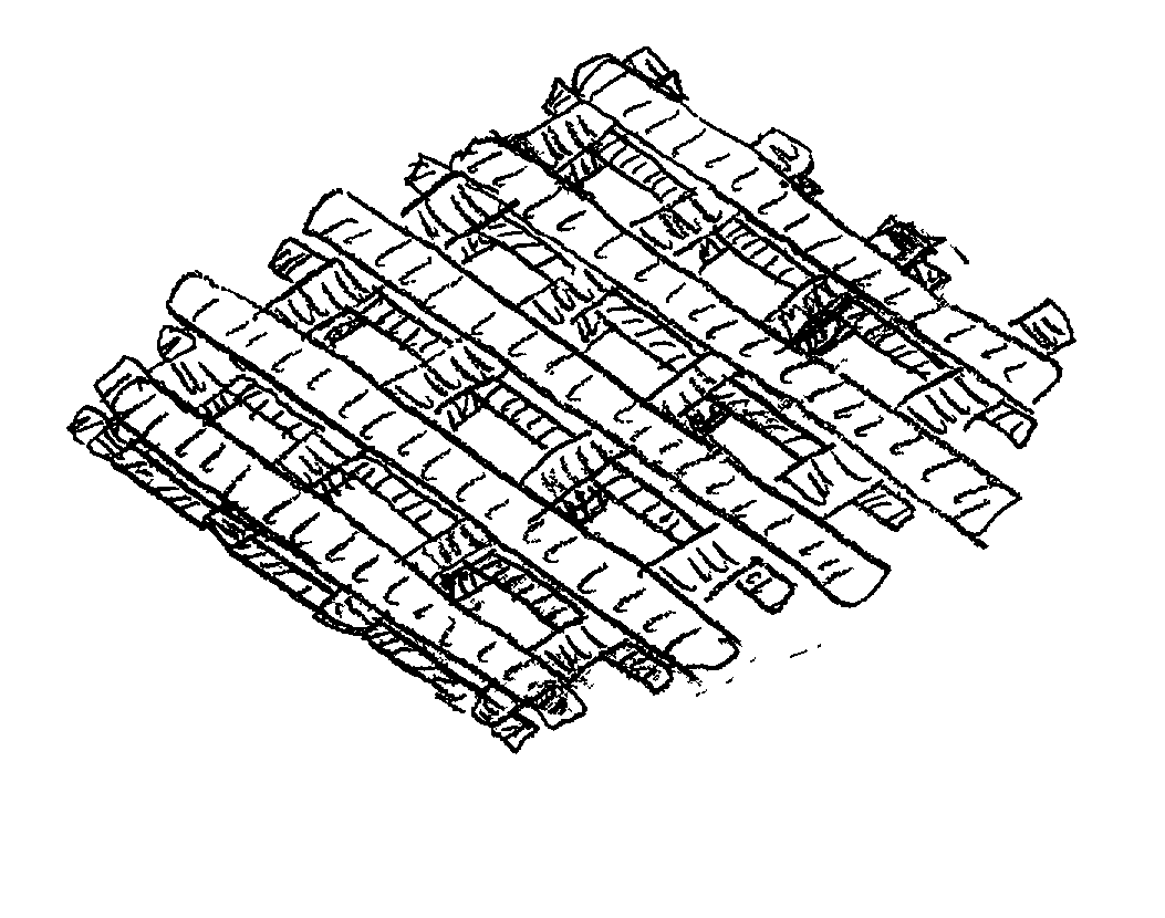
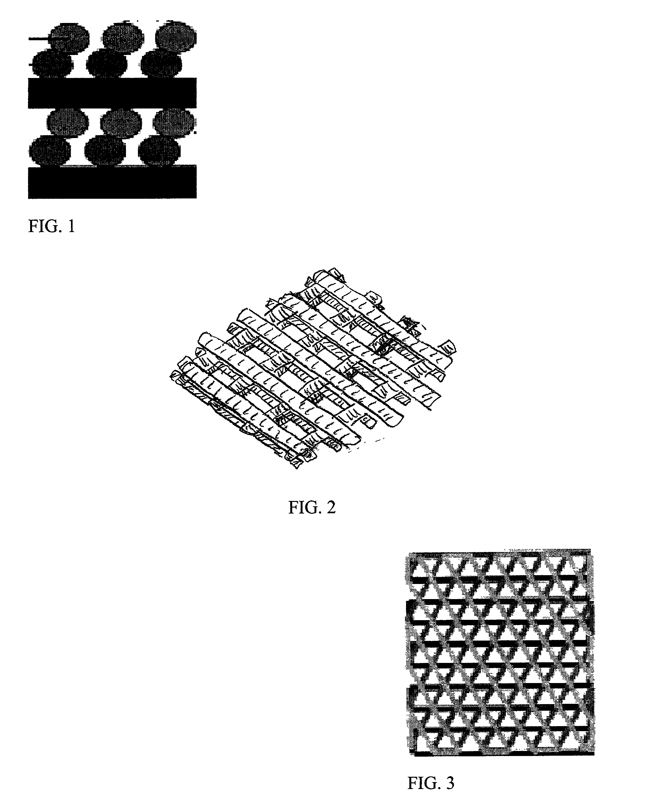
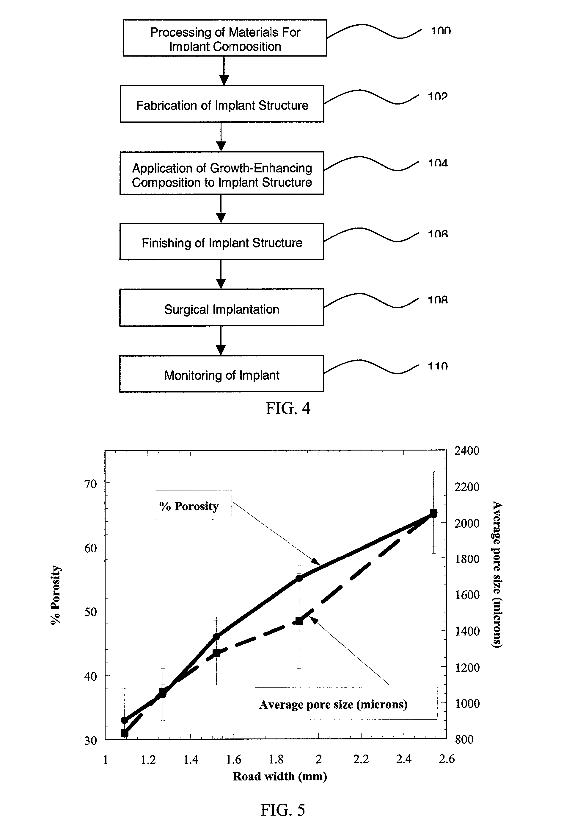
[0054] Porous test samples of PMMA and PBT were fabricated using these process conditions. A series of 1" diameter PMMA test samples were fabricated with raster road widths varying from 1.09 mm (0.0429") to 2.54 mm (0.1"). In previous experiments, it was observed that the nominal raster road width obtained for a 0.41 mm (0.016") tip was 0.64 to 0.76 mm. That is, although the material is extruded in a ribbon of substantially circular cross-section, upon deposition the material will settle somewhat to form a ribbon having, for ...

example 3

[0058] Tests were performed to determine the effectiveness of impregnating a porous specimen with an osteoinductive polymer / ceramic blend. For example, polycarbonate specimens having a series of through holes were tested. The specimens were impregnated with blend consisting of polycaprolactone (Tone-polyol 0260 from Union Carbide) and polycaprolactone mixed with 3.beta. calcium phosphate. Polycaprolactone is a biocompatible liquid, however, other biocompatible liquids, such as copolymers of 50:50 polylactic-polyglycolic acid may also be used.

[0059] The blends were heated to about 80-100.degree. C. to enable an easy flow. The specimens were impregnated with the heated blends and covered with a thin sheet of mylar. A vacuum was applied on the specimens so that the mylar sheet collapsed around the polycarbonate sheet and held the impregnated blend in place. On cooling, the blend solidified and stayed inside the pores.

[0060] Using the above technique, several more porous test specimens ...


PUM

PropertyMeasurementUnit
pore sizeaaaaaaaaaa
pore sizeaaaaaaaaaa
temperaturesaaaaaaaaaa

Abstract

The present invention relates to biomedical implants for bone substitution and replacement applications. The implant includes a strong, porous polymeric or thermoplastic compositions and growth-enhancing compositions.

Description

[0001] This application is based on, and claims the benefit of, co-pending United States Provisional Application Serial No. 60 / 259,348, filed on Jan. 2, 2001, and entitled "Biocompatible and Osteoinductive Biomedical Implants for Load Bearing Tissue Engineering Applications" and co-pending United States Provisional Application Serial No. 60 / 337,577 filed on Nov. 5, 2001, and entitled "Freeform Fabrication of Two-Step Biodegradable Porous Bone Prostheses."[0003] The present invention relates to biocompatible polymer-ceramic compositions and structures for use as biomedical implants for bone replacement and bone substitution treatment, particularly with load-bearing applications such as spinal implants.BACKGROUND OF INVENTION[0004] As the life expectancy of human beings has increased, so has the need for repair and replacement of bone structures within a body. Implants made from metals, such as titanium alloys, are known. Although such implants are strong, their use presents many prob...

Claims


Application Information

Patent Timeline
Patent Type & Authority Applications(United States)
IPC IPC(8): A61L27/00A61F2/44A61L27/44A61L27/46A61L27/48A61L27/56A61L27/58A61L31/12A61L31/14B29C47/06C08L3/18C08L33/12C08L67/02C08L71/12
CPCA61L27/446A61L27/48A61L27/56A61L31/125A61L31/129A61L31/146A61L27/58A61L27/54A61F2/28C08L71/12C08L67/04C08L67/02C08L33/12A61L31/18A61L31/16A61B17/58
Inventor VAIDYANATHAN, K. RANJIWALISH, JOSEPHCALVERT, PAUL D.
Owner THE UNITED STATES OF AMERICA AS REPRESENTED BY THE SECRETARY OF THE NAVY
Why Eureka
Try Eureka