Dopant Precursors and Processes

a technology of precursors and dopants, applied in the field of doped silicon and silicon alloy films, can solve the problems of difficult selection and inability to meet the requirements of the desired dopant species

Inactive Publication Date: 2002-11-21
ASM IP HLDG BV
View PDF0 Cites 84 Cited by
  • Summary
  • Abstract
  • Description
  • Claims
  • Application Information

AI Technical Summary

Problems solved by technology

Each of these processes has limitations and drawbacks.
For instance, the use of conventional dopant precursors often introduces unwanted elements.
In the case of hydride dopant precursors, such as diborane and phosphine, various partially hydrogenated species formed during ion implantation create a mass envelope from which it is difficult to select the desired dopant species.
This difficulty arises from the very small total mass of the fragments and the differences in mass between the various hydrogenated species (e.g., PH.sub.2.sup.+, PH.sup.+, P.sup.+, etc.), as well as the any overlap in mass between isotopes (e.g., boron has two stable isotopes with high natural abundancy, .sup.11B and .sup.10B).
The use of hydride dopant precursors for in situ CVD and diffusion source doping often has drawbacks, including: (1) poor dopant incorporation at low film deposition temperature (particularly for arsenic), (2) segregation of dopant atoms along grain boundaries in polycrystalline silicon-based materials, (3) decreased deposition rate of polycrystalline materials as the concentration of in situ dopant precursors is increased, particularly at low temperature, (4) low percentage of electrically active dopant species relative to the total concentration of dopant atoms present within the silicon-based material, particularly for low deposition temperature, requiring separate activation steps that consume thermal budget, (5) poor control over the distribution of the dopant atoms following subsequent thermal processing to drive the dopant and form a p-n junction arising from multiple diffusion pathways available due to the partially incorporated nature of the dopant atoms (i.e., dopant atoms are substitutionally incorporated within the crystalline framework of the silicon-based material as well as incorporated along grain boundaries and / or the surface of the film), and / or (6) limitations on the total concentration of electrically activated dopant atoms that can be incorporated within the silicon-based material as a function of solid solubility, particularly at low deposition temperature.
In addition to the problems cited above for the use of hydride dopant sources, halide sources entail other difficulties such as contamination of the silicon-based material with halide elements, particularly at low deposition temperature, and / or difficulty in delivering the dopant source to the reactor chamber as a function of precursor volatility.
This can also introduce problems with repeatability.
The use of trisilylarsine and trisilylphosphine as dopants is disclosed in U.S. Patent No. 4,910,153, but that patent does not address the problems discussed above which are encountered when doping non-hydrogenated Si-containing materials or when doping crystalline Si-containing materials, such as polysilicon and epitaxial silicon.
U.S. Patent No. 4,200,666 concerns the deposition of hydrogenated silicon nitride using trisilylamine, but does not disclose methods for making non-hydrogenated Si-containing materials .
Thus, a number of problems remain with respect to making Si-containing films such as silicon alloys and doped amorphous silicon, polysilicon, and epitaxial silicon.

Method used


Image

  • Dopant Precursors and Processes
  • Dopant Precursors and Processes

Examples


examples 1-3

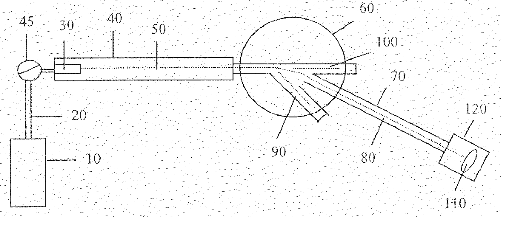
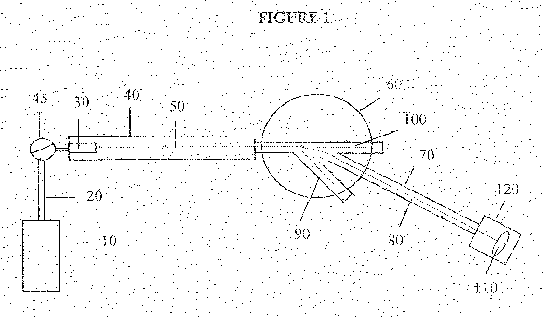
[0051] A tube furnace having an inlet and outlet was equipped with a pre-mix chamber and mass flow controller. Three Si substrates were placed along the length of the furnace. The furnace was evacuated and heated to a temperature of about 575.degree.C. Trisilylphosphine gas was introduced into the furnace at a flow rate of about 5-10 standard cubic centimeters per minute (sccm) and a pressure of about 0.001 torr, and continued for about 15 minutes. The trisilylphosphine flowed along the length of the furnace to the outlet, thereby depositing Si-containing films on each of the three substrates. The substrate of Example 1 was closest to the inlet and the substrate of Example 3 was closest to the outlet.

[0052] All three films were polycrystalline and had a thickness in the range of about 500 to about 1000 . The approximate composition (.+-.1 atomic %) of each of the deposited films was measured by Rutherford backscattering spectroscopy (RBS). Hydrogen concentration was measured using ...

example 4

[0054] A Si wafer substrate is etched in a solution of dilute hydrofluoric acid, rinsed and dried, then loaded into an Epsilon E2500.TM.reactor system (available commercially from ASM America, Inc. of Phoenix, Arizona) and subjected to a hydrogen bake at 900.degree.C at atmospheric pressure under a flow of 80 standard liters per minute (slm) of ultra-pure hydrogen for 2 minutes. The substrate is then allowed to reach thermal equilibrium at 600.degree.C at 40 Torr pressure under a flow of 20 slm of ultra-pure hydrogen gas. The steps of etching, drying, rinsing, and baking render the single crystal surface active for epitaxial film growth.

[0055] Pure hydrogen gas is then passed through a liquid mixture of 99.999 weight % trisilane and 0.001 weight % trisilylarsine in order to deliver a vapor comprising trisilane and trisilylarsine to the heated substrate. The liquid mixture is maintained at room temperature using a water bath around the bubbler containing the mixture. The vapor is in...


PUM

PropertyMeasurementUnit
temperatureaaaaaaaaaa

Abstract

<heading lvl="0">Abstract of Disclosure< / heading> Silicon alloys and doped silicon films are prepared by chemical vapor deposition and ion implantation processes using Si-containing chemical precursors as sources for Group III and Group V atoms. Preferred dopant precursors include (H3Si)3-xMRx, (H3Si)3N, and (H3Si)4N2, wherein R is H or D, x = 0, 1 or 2, and M is selected from the group consisting of B, P, As, and Sb. Preferred deposition methods produce non-hydrogenated silicon alloy and doped Si-containing films, including crystalline films.

Description

Cross Reference to Related Applications[0001] This application claims priority to U.S. Provisional Application No. 60 / 268,337, filed February 12, 2001; U.S. Provisional Application No. 60 / 279,256, filed March 27, 2001; U.S. Provisional Application No. 60 / 311,609, filed August 9, 2001; U.S. Provisional Application No. 60 / 323,649, filed September 19, 2001; U.S. Provisional Application No. 60 / 332,696, filed November 13, 2001; U.S. Provisional Application No. 60 / 333,724, filed November 28, 2001; and U.S. Provisional Application No. 60 / 340,454, filed December 7, 2001; all of which are hereby incorporated by reference in their entireties. This application is related to, and incorporates by reference in their entireties, co-owned and co-pending U.S. Patent Application Serial Numbers: 10 / 074,563; 10 / 074,722; 10 / 074,633; 10 / 074,564; and 10 / 074,534, all of which were filed on February 11, 2002.Background of InventionField of the Invention[0002] This invention relates generally to silicon-cont...

Claims


Application Information

Patent Timeline
Patent Type & Authority Applications(United States)
IPC IPC(8): C23C16/24C23C16/02C23C16/42C30B25/02H01L21/20H01L21/205H01L21/28H01L21/285H01L21/316H01L21/331H01L21/337H01L21/425H01L21/469H01L21/8238H01L27/092H01L29/51H01L29/737H01L29/78H01L31/18H01L31/20
CPCB82Y10/00Y02E10/547C23C16/0272C23C16/22C23C16/24C23C16/30C23C16/308C23C16/325C23C16/345C23C16/36C23C16/56C30B25/02C30B29/06H01L21/02422H01L21/0243H01L21/0245H01L21/0251H01L21/02529H01L21/02532H01L21/02576H01L21/02579H01L21/02592H01L21/02595H01L21/02598H01L21/0262H01L21/02667H01L21/2257H01L21/28035H01L21/28044H01L21/28194H01L21/28525H01L21/28556H01L21/3185H01L21/32055H01L28/84H01L29/127H01L29/51H01L29/517H01L29/518H01L29/66181H01L29/66242H01L31/1804H01L31/182H01L31/202Y02E10/546Y10S438/933B82Y30/00Y02P70/50H01L21/02271H01L21/02211H01L21/0217
Inventor TODD , MICHAEL A.
Owner ASM IP HLDG BV
Why Eureka
Try Eureka