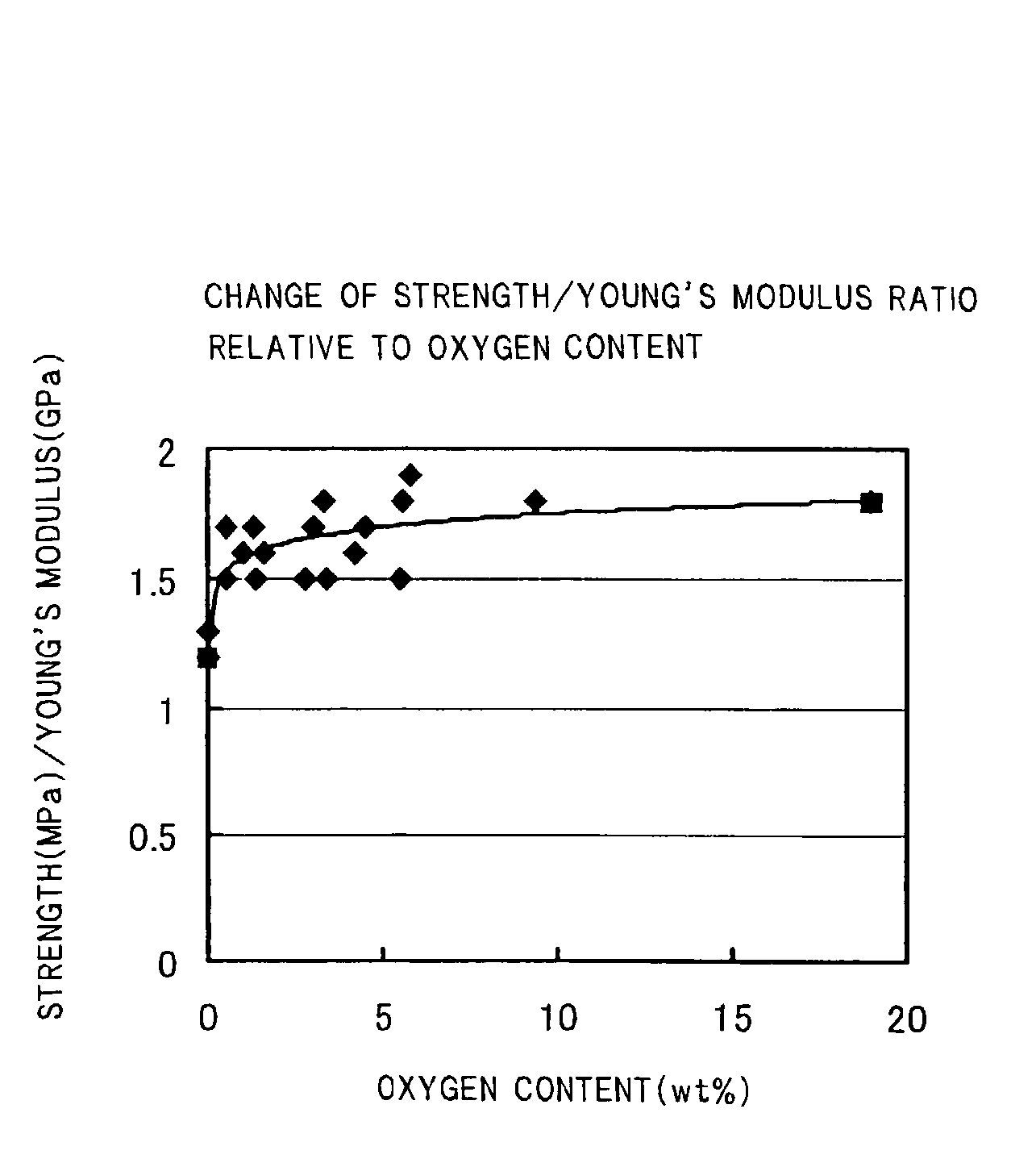
Cellulase preparation containing nonionic surfactant and method of treating fiber

a cellulase and surfactant technology, applied in catalyst activation/preparation, machines/engines, natural mineral layered products, etc., can solve the problems of undissolved problems in the production cost, high cost, thermal conductivity,

Inactive Publication Date: 2003-01-30
NGK INSULATORS LTD
View PDF0 Cites 33 Cited by
  • Summary
  • Abstract
  • Description
  • Claims
  • Application Information

AI Technical Summary

Benefits of technology

0039] As the fluid containing silicon and oxygen, there can be used a fluid composed mainly of, for example, a silicon alkoxide, a silica sol, water glass or the like. These main components may be mixed as necessary. The heat treatment after coating can be conducted at 50 to 1,400.degree. C. for 10 minutes to 4 weeks. The thickness of the oxygen-containing phase formed by coating can be controlled appropriately by adjusting the silicon concentration in the fluid. The thickness of the phase can be made large by repeating the immersion in the fluid and the subsequent drying. The thickness of the phase can be controlled also by controlling the speed of taking out the to-be-coated material from the fluid.
0040] In the above process for producing a silicon carbide-based porous body according to the present invention, the heat treatment conducted after the coating of the surfaces of the silicon carbide particles and the metallic silicon after

Problems solved by technology

There are problems, however, that this method brings a high cost since a very high firing temperature is required to be employed in order to vaporize silicon carbide, and that the yield after firing is reduced since a material of high thermal expansion coefficient is required to be fired at a high temperature as well.
This honeycomb filter has a sufficient mechanical strength but has yet undissolved problems in the production cost, thermal conductivity, etc.
; however, when the sintered body produced by the technique is used, for example, as a diesel particulate filter (DPF) for removing the particulates contained in the exhaust gas emitted from a diesel engine and the particulates collected by and deposited on the filter are burnt for reactivation of the filter, there occurs local heat generation caused by the low thermal conductivity of the filter, which has incurred the destruction of the filter.
Further, the filter shown in JP-B-61-13845 and JP-B-61-13846 is porous but is a bottomed cylindrical material having a large partition wall thickness of 5 to 20 mm; therefore, there is a problem that the filter is not usable under the high space velocity (SV) condition like as a filter for purification of automobile exhaust gas.
The honeycomb st

Method used


Image

  • Cellulase preparation containing nonionic surfactant and method of treating fiber
  • Cellulase preparation containing nonionic surfactant and method of treating fiber
  • Cellulase preparation containing nonionic surfactant and method of treating fiber

Examples


example 2

(Example 2)

[0047] The operation up to molding was conducted in the same manner as in Example 1. The resulting honeycomb molded material was kept at 550.degree. C. for 5 hours while air was allowed to flow; then, the air was switched to Ar and the temperature was increased to 1,000.degree. C. to conduct calcination for debindering, while keeping it as it was. Thereafter, firing was conducted in an Ar atmosphere at 1,450.degree. C. for 2 hours to produce a silicon carbide sintered body of porous honeycomb structure. The crystal phase of the sintered body was examined by X-ray diffraction, which confirmed that the sintered body was composed of SiC, Si and SiO.sub.2.

(Examples 3 to 9)

[0048] The operation up to molding was conducted in the same manner as in Example 1. The resulting honeycomb molded material was calcinated for debindering, in a low-oxygen content atmosphere at 550.degree. C. for 3 hours and then firing was conducted in a non-oxidative atmosphere of reduced pressure at 1,45...

examples 16 and 17

(Examples 16 and 17)

[0052] The operation up to firing was conducted in the same manner as in Examples 3 to 9, to produce silicon carbide sintered bodies of porous honeycomb structure. Then, each sintered body was immersed in a silica sol (SiO.sub.2 content: 4 or 20% by weight) and taken out slowly to coat the sintered body with the silica sol. Successively, each coated sintered body was heat-treated in air at 750.degree. C. for 1 hour to produce silica-coated silicon carbide sintered bodies of porous honeycomb structure.

[0053] There was no macroscopic or microscopic change in the honeycomb structures before and after the silica coating. The crystal phase of each sintered body after the silica coating was examined by X-ray diffraction, which confirmed that the sintered body after the silica coating was composed of SiC, Si and SiO.sub.2.


PUM

PropertyMeasurementUnit
Percent by massaaaaaaaaaa
Temperatureaaaaaaaaaa

Abstract

It is directed to a silicon carbide-based porous body, wherein said body is a porous one which contains silicon carbide particles as an aggregate and metallic silicon, and has an oxygen-containing phase at the surfaces of silicon carbide particles and/or metallic silicon or in the vicinity of the surfaces thereof. The silicon carbide-based porous body contains refractory particles such as silicon carbide particles or the like and yet can be produced at a relatively low firing temperature at a low cost, has a high thermal conductivity, and is superior in oxidation resistance, acid resistance, chemical resistance to ash and particulates.

Description

[0001] The present invention relates to a silicon carbide-based porous body used in a filter for purification of automobile exhaust gas, a catalyst carrier, or the like, as well as to a process for production of such a silicon carbide-based porous body.[0002] Porous honeycomb structures are in wide use as a filter for capturing and removing the particulate substance present in a dust-containing fluid (e.g. exhaust gas emitted from diesel engine), or as a catalyst carrier for loading thereon a catalyst component capable of purifying the harmful substances present in an exhaust gas. It is known that as a material constituting such a honeycomb structure, there are used refractory particles such as silicon carbide (SiC) particles and the like.[0003] As a specific technique related thereto, there is disclosed, in, for example, JP-A-6-182228, a porous, silicon carbide-based catalyst carrier of honeycomb structure, obtained by using, as a starting material, a silicon carbide powder having ...

Claims


Application Information

Patent Timeline
IPC IPC(8): F01N3/02B01D46/00B01D46/24B01D53/86B01D53/88B01J27/224B01J35/04B01J37/00C04B35/565C04B35/638C04B38/00C04B38/06C04B41/50C04B41/85F01N3/022F01N3/28
CPCB01D46/0001Y10T428/2991B01D46/2429B01D46/2448B01D53/885B01D2046/2496B01J27/224B01J37/0018C04B35/565C04B35/6365C04B35/638C04B38/0006C04B41/009C04B41/5035C04B41/5089C04B41/85C04B2111/00793C04B2111/0081C04B2235/3418C04B2235/3826C04B2235/428C04B2235/5436C04B2235/6021C04B2235/668C04B2235/72C04B2235/723C04B2235/80C04B2235/96C04B2235/9607C04B2235/9669C04B2235/9684C04B2235/9692F01N3/0222F01N3/2803F01N2330/00B01D46/2425Y10T428/24149Y10T428/2982Y02T10/20C04B41/4519C04B41/4556C04B35/14C04B38/00C04B41/0072C04B35/573Y10T428/249986Y10T428/249953Y02T10/12B01D46/2498B01D46/24495
Inventor TOMITA, TAKAHIROICHIKAWA, SHUICHIKAWASAKI, SHINJISAKAI, HIROAKI
Owner NGK INSULATORS LTD
Why Eureka
Try Eureka