Method for making a fuel cell with large active surface and reduced volume

Inactive Publication Date: 2005-01-27
COMMISSARIAT A LENERGIE ATOMIQUE ET AUX ENERGIES ALTERNATIVES
View PDF9 Cites 28 Cited by
  • Summary
  • Abstract
  • Description
  • Claims
  • Application Information

AI Technical Summary

Problems solved by technology

The power densities obtained at one individual cell are very low and are generally insufficient to allow electrical equipment to function.
The difficulty resides in assembling the micro-electrode with the thin film of proton-conducting material.
However, the performance of a device of this type is limited by the poor cohesion of the various layers, thereby creating a strong interfacial resistance, and by a very weak dispersion of the catalyst, the latter being finely divided, in order to obtain a strongly electron-conducting deposit.
This technique has a certain number of drawbacks linked in particular to the properties of nickel.
Specifically, nickel is sensitive to corrosion phenomena caused by the strongly acidic nature of the proton conductor.
Moreover, the catalyst is poorly dispersed at the perforated nickel layer, which has a low capacity to draw a homogeneous dispersion of the reducing agent over the catalyst.
Finally, this technology entails a low probability of triple points being present.
This invention has two main drawbacks: firstly the fragility of the polymer substrate, in particular when it is treated using aggressive vacuum deposition techniques, and secondly the poor electrochemical performance, linked in particular to the lack of active surface area and also to the fragility of the catalyst deposit formed directly on the proton exchange membranes.
All of the architectures presented have the particular feature of being entirely planar, which means that it is therefore n

Method used


Image

  • Method for making a fuel cell with large active surface and reduced volume
  • Method for making a fuel cell with large active surface and reduced volume
  • Method for making a fuel cell with large active surface and reduced volume

Examples


example

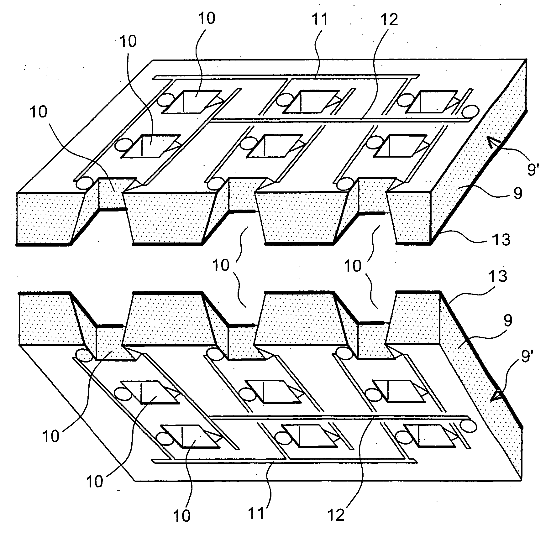
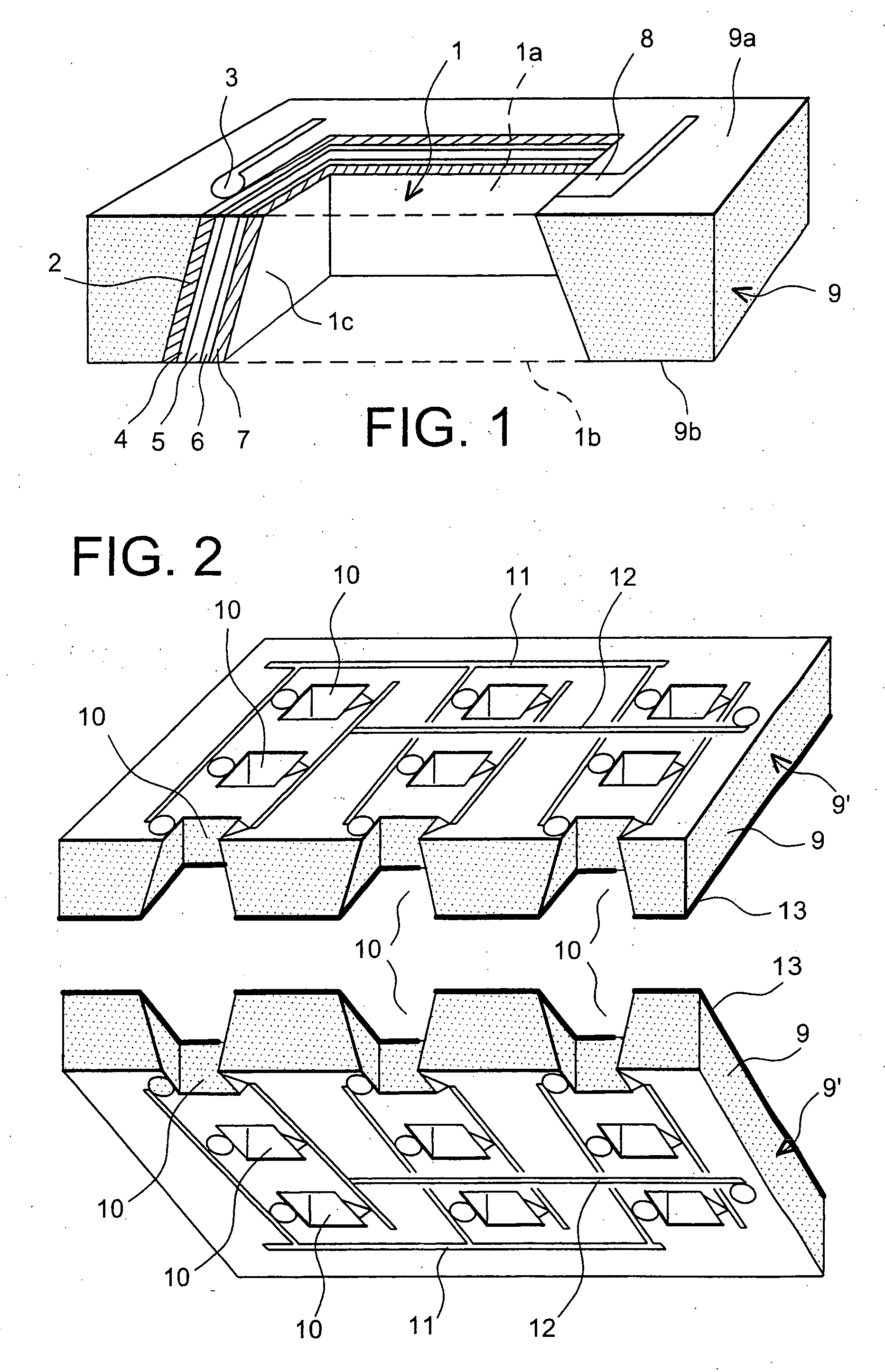
The objective is to develop an active surface area of 350 cm2 for a visible surface area of 25 cm2 and an energy of 10 Wh.

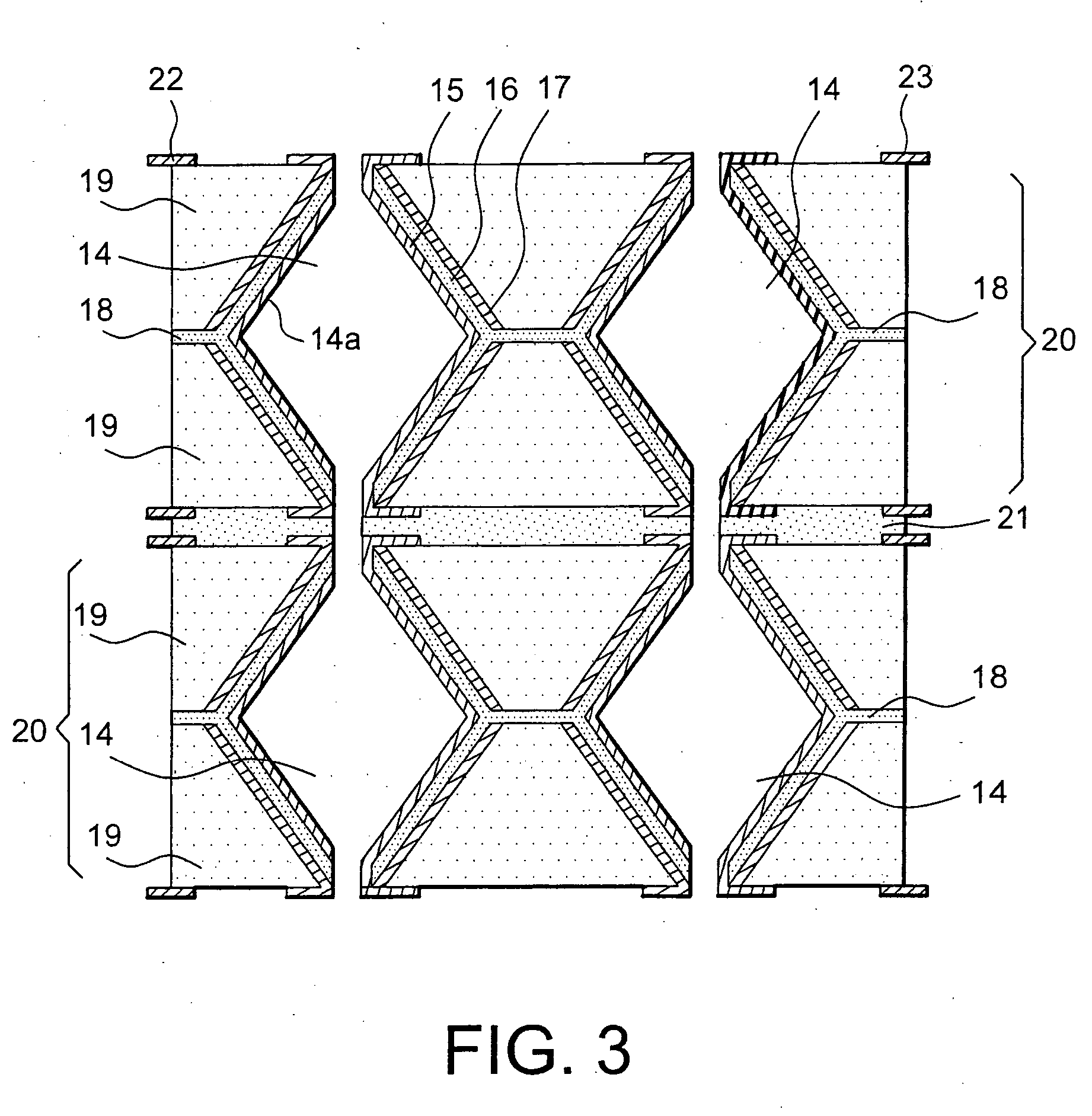
To do this, the substrate is a single-crystal silicon wafer with a thickness of 400 micrometres and a visible surface area of 25 cm2, on which is etched a network of holes. The holes are formed by plasma etching and have a square cross section with a side length of 100 micrometres, an opening surface area of 56%, the opening surface area corresponding to the ratio between the hollow surface area and the total surface area, and a reduction factor of 80% between the entry surface area and the exit surface area of the holes. Consequently, the developed surface area is seven times larger than the visible surface area. The thin films required to form a fuel cell are deposited in succession on the flanks of the holes, these films specifically comprising: an anode comprising, in the context of the present example, a current collector and a catalyst layer deposited b...


PUM

PropertyMeasurementUnit
Compositionaaaaaaaaaa
Adhesion strengthaaaaaaaaaa
Shapeaaaaaaaaaa

Abstract

The present invention relates to a process for producing a fuel cell, comprising a step of forming a plurality of holes (10) in at least two substrates (9); each hole is in the seat of an individual fuel cell, the said holes having a particular geometry, such as a shape of a truncated cone or a truncated pyramid shape.
The various individual cells are then electrically connected by networks of electrical connections (11, 12) and are supplied via a reactant distribution network, the assembly formed by a substrate (9), the cells and the networks constituting a base module (9′). Finally, at least two base modules (9′) are assembled, the individual cells of each base module being positioned facing the individual cells of the adjacent base module(s).

Description

TECHNICAL FIELD The present invention relates to a process for producing a fuel cell with a large active surface area and a small volume. The invention therefore deals with the field of fuel cells, and more particularly fuel cells with a solid polymer membrane as electrolyte, such as PEMFCs (“Proton Exchange Membrane Fuel Cells”) and DMFCs (“Direct Methanol Fuel Cells”). Fuel cells of the solid polymer electrolyte type are employed, in particular, in land, air and water transport and in particular in land vehicles, which are currently the subject of numerous development programmes aimed at finding alternatives to the use of batteries in electrical vehicles. PRIOR ART In general, fuel cells are composed of a stack of individual cells. Each of these cells comprises an anode and a cathode positioned on either side of an electrolyte. The fuel, such as hydrogen H2 for hydrogen fuel cells, is oxidized at the anode, thereby producing protons and electrons. The electrons rejoin the exte...

Claims


Application Information

Patent Timeline
IPC IPC(8): H01M4/86H01M8/02H01M8/04H01M8/10H01M8/24
CPCH01M4/8605H01M8/0284H01M8/1002H01M8/1011Y10T29/49108H01M8/241H01M8/2455Y02E60/523H01M8/1097H01M8/1007Y02E60/50Y02P70/50H01M8/2404
Inventor ARROYO, JEANBLOCH, DIDIERLAURENT, JEAN-YVESMARSACQ, DIDIER
Owner COMMISSARIAT A LENERGIE ATOMIQUE ET AUX ENERGIES ALTERNATIVES
Why Eureka
Try Eureka