
Methods of making a niobium metal oxide and oxygen reduced niobium oxides

a technology of which is applied in the field of making niobium metal oxide and oxygen reduction niobium oxides, can solve the problems of low esr, high capacitance (i.e., high volumetric efficiency), and difficulty in working, so as to achieve high esr, low leakage, and high accessible surface area to volume ratio

Active Publication Date: 2005-02-03
GLOBAL ADVANCED METALS USA
View PDF71 Cites 37 Cited by
  • Summary
  • Abstract
  • Description
  • Claims
  • Application Information

AI Technical Summary

Benefits of technology

Another feature of the present invention is to provide oxygen reduced niobium oxides having improved sintered crush strength, porosity, green strength, and flow characteristics.
The present invention also relates to high capacitance capacitors having low DC leakage made from valve metal oxide particles.

Problems solved by technology

In particular, fine powders, for instance, having particle sizes of 0.1-200 microns, can prove difficult to work with and thus, methods to agglomerate or granulate fine metal powder have been developed.
However, these methods have the possibility that some incomplete reactions may occur that yield a sub-optimal material such as NbO2 that is interspersed within and difficult to separate from the NbO.
However, coarsening of the particles tends to be accompanied by densification of the particles which reduces the surface area (reduced capacitor capacitance).
Thus, the production of agglomerated particles having a large surface area, suitable cohesive strength, and uniform porosity that enable the production of a valve metal capacitor having both high capacitance (i.e., high volumetric efficiency) and low ESR is considerably difficult using capacitor grade powders made by conventional methods.
In addition, conventional methods of preparing a valve metal suboxide powder typically produce powder particles having a relatively rough, irregular surface texture.
Residual organics can result in high levels of residual carbon in the finished capacitors, causing high DC leakage of the capacitors.
Niobium is becoming one of the alternatives to tantalum but as the industry has realized, niobium is not a complete substitute for tantalum due to niobium not providing the same electrical properties.
The acid leaching step complicates the manufacturing process and leads to the manufacturing process being more expensive.
In some processes, the treatment steps can cause a loss of surface area and other treatment steps can cause a loss of flow properties and a decline in other favorable properties generally useful in the fabrication of capacitor anodes.
However, in any effort to improve upon this property, other properties can be affected such as the surface area, pore structure, pore size distribution, flow properties, and the like.
Metallic and non-metallic contamination tends to degrade the dielectric oxide film in metal capacitors.
While high sintering temperatures serve to remove some volatile contaminants, high temperatures tend to shrink the porous body reducing its net specific surface area and thus the capacitance of the resulting capacitor.
In addition to being relatively expensive due to the historically high cost of niobium metal, reduction methods using niobium metal offer significant challenges in controlling morphology and microstructure of the oxygen reduced final product (e.g., NbO) to obtain performance characteristics, such as high CV / g.
In addition to limited control over final product morphology, conventional methods of preparing niobium suboxide that use solid getter materials other than niobium metal, such as tantalum and magnesium, have other drawbacks.
For instance, the final niobium suboxide product can become contaminated in the reduction process by unreacted or residual getter material and / or oxidized getter material being mixed in with the niobium suboxide.
The likelihood of contamination is increased when the getter material is physically contacted with the starting niobium oxide such as by homogenizing, blending, mixing or the like.
Also, getter materials used in conventional reduction reactions typically have high atomic weight and particles that provide a relatively low surface area with which the oxygen can react.
Preparation of the final product by decontaminating the niobium suboxide by screening or acid leaching the niobium suboxide, for example, becomes more difficult and more waste is produced.

Method used


Image

  • Methods of making a niobium metal oxide and oxygen reduced niobium oxides
  • Methods of making a niobium metal oxide and oxygen reduced niobium oxides
  • Methods of making a niobium metal oxide and oxygen reduced niobium oxides

Examples


example 1

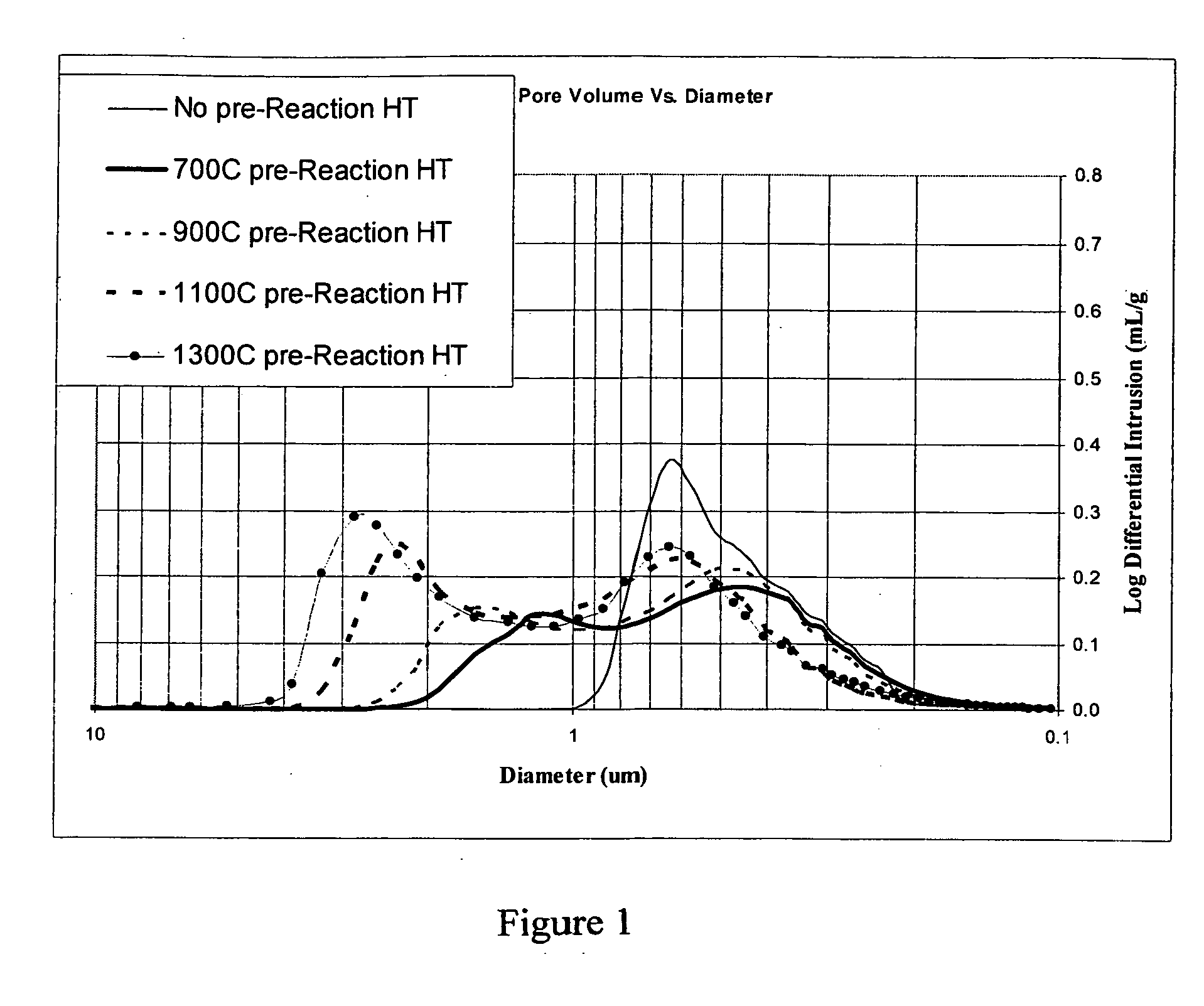
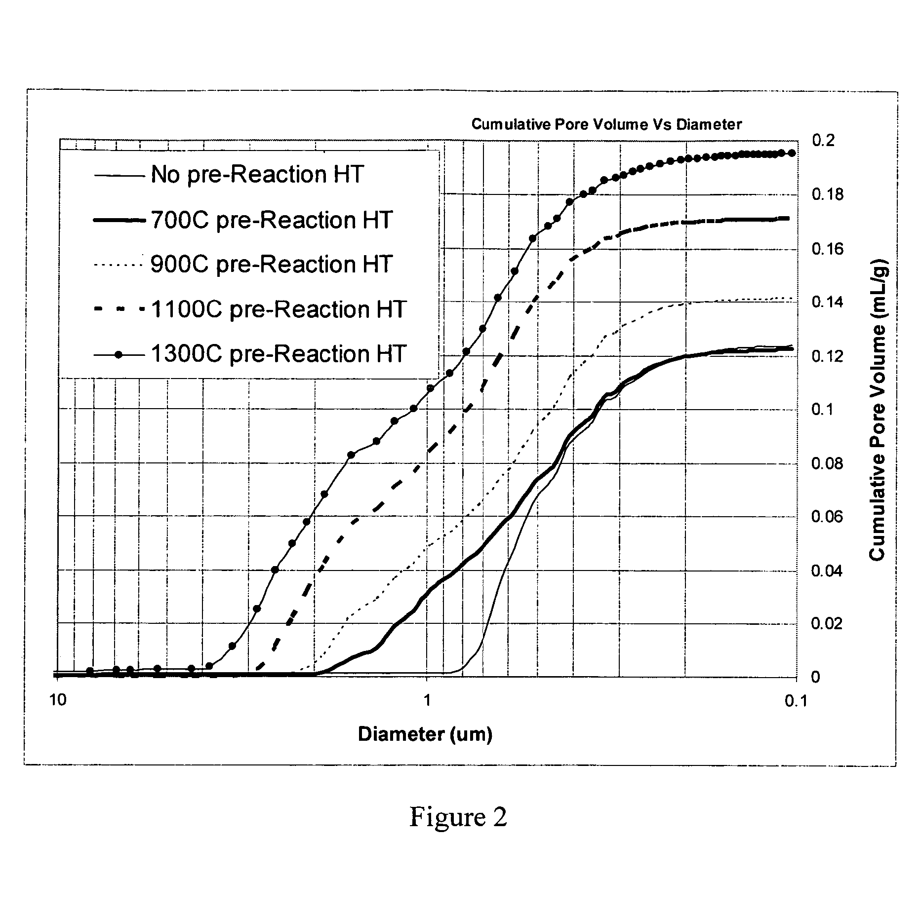
According to an embodiment of the invention, niobium powder (200 g) having a BET surface area of 4.1 m2 / g and starting niobium oxide (161 g), i.e., niobium pentoxide, with a BET surface area of 1.3 m2 / g were mixed together to form a powder mixture. The powder mixture was then granulated and screened to a granular size of about −40 mesh. The granular powder mixture was then placed into a vacuum heat treatment furnace and heated under vacuum to about 700° C. for about 2 hours. Hydrogen gas was then admitted to the furnace to a pressure of about 960 Torr. The temperature in the furnace was then brought to about 850° C. and held for about 1 hour. After formation, the oxygen reduced niobium oxide was tested for certain properties which are set forth in Table 1. Three more trials were made with three more sample lots of niobium powder and starting niobium oxide wherein the above described method was repeated with heat treatment temperatures of 900, 1,100, and 1,300° C., respectively. In ...

example 2

According to an embodiment of the invention, niobium hydride powder (20 g) having a BET surface area of 3.9 m2 / g and starting niobium oxide (16.1 g), i.e. niobium pentoxide, with a BET surface area of 3.9 m2 / g were mixed together to form a powder mixture. The powder mixture was then attritor milled (comilled) in water for 2 hours using {fraction (3 / 16)} Nb media. The powder slurry was vacuum dried at 120° C. and granulated by passing the dried powder over a 50 mesh screen. The granular powder mixture was then placed into a vacuum heat treatment furnace and heated to 1100° C. for about 2 hours. The temperature in the furnace was then brought to about 850° C. and hydrogen gas was admitted to the furnace to a pressure of about 960 Torr and held for about 1 hour. After formation, the oxygen reduced niobium oxide was tested for certain properties which are set forth in Table 2. In addition, sample lots of niobium hydride and niobium pentoxide were mixed as described above without the at...

example 3

According to an embodiment of the invention, niobium hydride powder (400 g) having a BET surface area of 3.9 m2 / g and starting niobium oxide (322 g), i.e. niobium pentoxide, with a BET surface area of 3.9 m2 / g were mixed together to form a powder mixture. The powder mixture was then attritor milled (comilled) in water for 2 hours using {fraction (3 / 16)}″ Nb media. The powder slurry was vacuum dried at 120° C. and granulated by passing the dried powder over a 50 mesh screen. In addition, some of the powder was passed over a 70 mesh, 100 mesh and 140 mesh screen. The sample passing through the appropriate screen was collected. The granular powder mixture was then placed into a vacuum heat treatment furnace and heated to 1400° C. for about 2 hours. The temperature in the furnace was then brought to about 850° C. and hydrogen gas was admitted to the furnace to a pressure of about 960 Torr and held for about 1 hour. After formation, the oxygen reduced niobium oxide powders were tested f...


PUM

PropertyMeasurementUnit
Temperatureaaaaaaaaaa

Abstract

Methods to at least partially reduce a niobium oxide are described wherein the process includes mixing the niobium oxide and niobium powder to form a powder mixture that is then heat treated to form heat treated particles which then undergo reacting in an atmosphere which permits the transfer of oxygen atoms from the niobium oxide to the niobium powder, and at a temperature and for a time sufficient to form an oxygen reduced niobium oxide. Oxygen reduced niobium oxides having high porosity are also described as well as capacitors containing anodes made from the oxygen reduced niobium oxides.

Description

BACKGROUND OF THE INVENTION The present invention relates to niobium and other valve metals and oxides thereof and more particularly to niobium oxides and methods to at least partially reduce niobium oxide and further to oxygen reduced niobium oxides and other valve metal oxides. The present invention relates to niobium oxides and other valve metal oxides useful, for instance, in the production of capacitors, sintered anode bodies, and the like. The present invention also relates to methods of making niobium oxide particles and other valve metal oxide particles. The present invention also relates to niobium, niobium powder, hydrided forms thereof, and electrolytic capacitors made therefrom. More particularly, the present invention relates to methods of preparing niobium or hydrided niobium feedstock to form suitable niobium powder or hydrided niobium for a variety of uses. Efforts are continually being made to improve the handling of metal powder, such as niobium powder. In partic...

Claims


Application Information

Patent Timeline
IPC IPC(8): C01G33/00
CPCC01G33/00C01P2004/03C01P2004/51C01P2004/61Y10T428/2982C01P2006/12C01P2006/14C01P2006/17C01P2006/40C01P2004/62
Inventor REED, DAVID M.VENIGALLA, SRIDHARKITCHELL, RICKY W.KRAUSE, STEPHEN J.ENMAN, HEATHER L.SCHULTZ, DORRAN L.KERCHNER, JEFFREY A.
Owner GLOBAL ADVANCED METALS USA
Learn More