Mgo vapor deposition material and method for preparation thereof

a technology vapor deposition layer, which is applied in the direction of vacuum evaporation coating, crystal growth process, polycrystalline material growth, etc., can solve the problem of reducing the efficiency with which the quantity of vapor deposition material can be used in the film formation process, affecting the film characteristics of mgo film, and poor efficiency of sulfur removal

Inactive Publication Date: 2005-03-03
MITSUBISHI MATERIALS CORP
View PDF3 Cites 19 Cited by
  • Summary
  • Abstract
  • Description
  • Claims
  • Application Information

AI Technical Summary

Benefits of technology

In addition, the present invention may consist of polycrystalline pellets with an average crystal grain diameter of 1 to 500 μm formed from the sintered MgO described above, comprising rounded air pockets with an average diameter of no more than 10 μm inside the crystal grains of the sintered pellets. In this type of MgO vapor deposition material, the sintered pellets of the polycrystalline MgO have a finely detailed crystalline structure, and the occurrence of defects at the crystal grain boundaries can be reduced, meaning the formed MgO film displays superior film characteristics.
Furthermore the present invention may comprise polycrystalline pellets formed from sintered polycrystalline MgO, in which the elemental concentration of Si is no more than 5000 ppm, the elemental concentration of Al impurities is no more than 300 ppm, the elemental concentration of Ca impurities is no more than 2000 ppm, the elemental concentration of Fe impurities is no more than 400 ppm, the elemental concentrations of Cr, V and Ni impurities are each no more than 50 ppm, the elemental concentrations of Na and K impurities are each no more than 30 ppm, the elemental concentration of C impurities is no more than 300 ppm, and the elemental concentration of Zr impurities is no more than 150 ppm. In this type of MgO vapor deposition material, the quantities of impurities contained within the formed MgO film are extremely low, meaning the film characteristics of the MgO film can be further improved.

Problems solved by technology

The method used for removing the electronegative element component such as sulfur requires a heat treatment at a temperature of at least 1400° C. in either a vacuum with a pressure of no more than 1.33×10⁻¹ Pa (10−3 Torr) or in an oxygen containing atmosphere, which is performed following crystal growth (pellet preparation) and prior to formation of the protective film, although in the case of polycrystals or single crystals produced using an electromelting method with a relative density of at least 90%, the efficiency of the sulfur removal was poor.
It is known that during film formation using either an electron beam deposition method or an ion plating method, the quantities of sulfur S, chlorine Cl, nitrogen N and phosphorus P discharged from the MgO vapor deposition material as impurities has a deleterious effect on the level of splash associated with that vapor deposition material.
In other words, as the quantities of sulfur S, chlorine Cl, nitrogen N and phosphorus P impurities increase, the level of splash also increases, and if the level of splash is high, then the degree of efficiency with which the quantity of vapor deposition material can be used in the film formation process decreases, resulting in an increase in material costs.
In addition, if the quantities of sulfur S, chlorine Cl, nitrogen N and phosphorus P impurities are high, then control of the crystal orientation and microstructure of the product film becomes difficult, and compact deposition of the MgO film onto the substrate is inhibited, meaning the film density tends to decrease.
If the density of the MgO film decreases, then various problems can arise including a reduction in the refractive index, a deterioration in the sputtering resistance, and deterioration in both the discharge characteristics and the insulating characteristics.
The reason for this requirement is that if sharp sections exist on the target material, then electrons tend to accumulate at those sections, meaning the argon ion bombardment is also concentrated on those sections, causing a phenomenon known as arcing, which causes non-uniformity in the product film, and consequently these sharp sections must be removed.

Method used


Image

  • Mgo vapor deposition material and method for preparation thereof
  • Mgo vapor deposition material and method for preparation thereof
  • Mgo vapor deposition material and method for preparation thereof

Examples


first embodiment

As follows is a detailed description of a MgO vapor deposition material according to the present invention and a production process therefor.

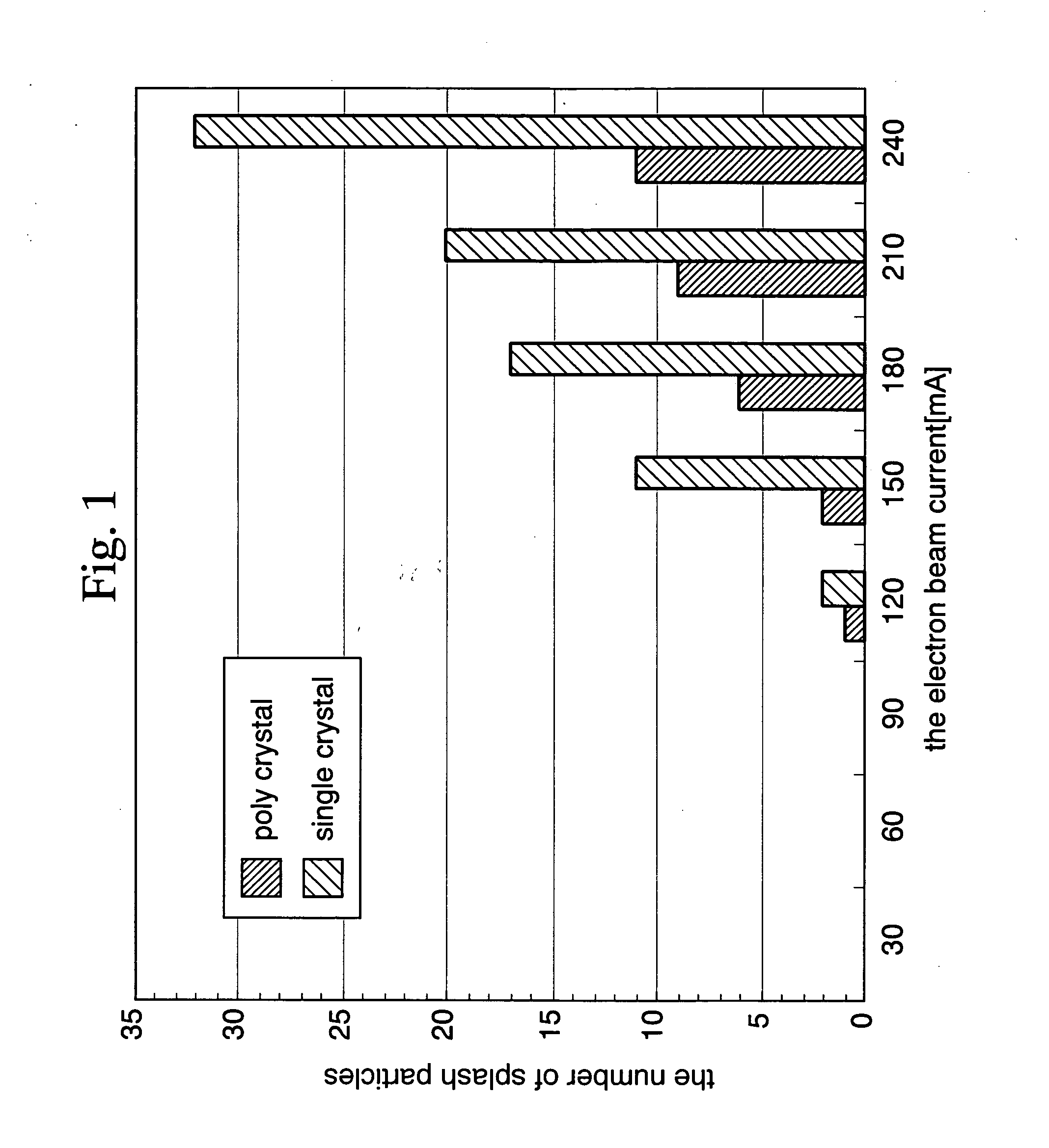
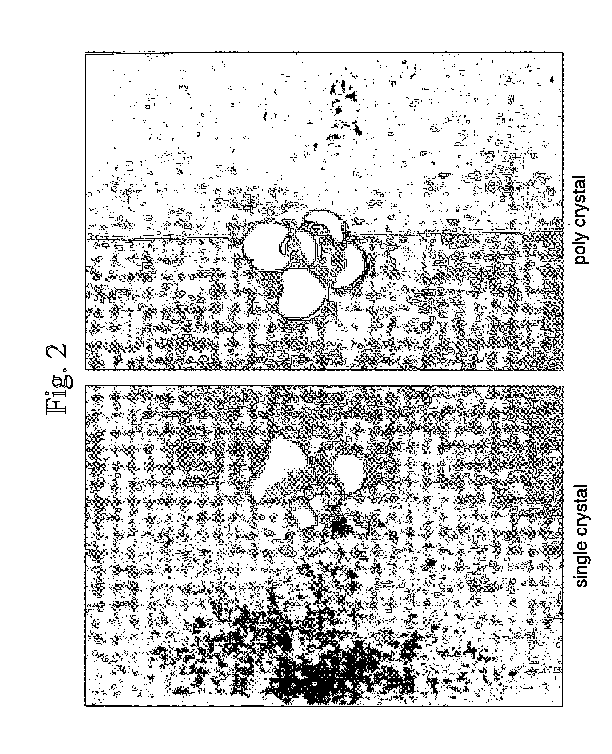
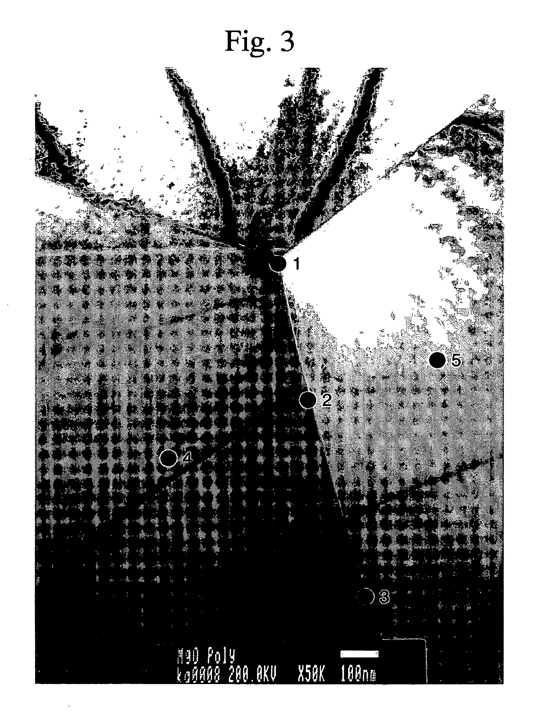
A MgO vapor deposition material of this embodiment comprises sintered pellets of polycrystalline MgO with an average sulfur S content of 0.01 to 50 ppm, an average chlorine Cl content of 0.01 to 50 ppm, an average nitrogen N content of 0.01 to 200 ppm and an average phosphorus P content of 0.01 to 30 ppm, as well as a MgO purity of at least 99.0%, and preferably at least 99.5%, and even more preferably at least 99.9%, and a relative density of at least 90%, and preferably at least 97%, and even more preferably at least 98%. Furthermore the average crystal grain diameter of the sintered pellets is from 1 to 500 μm, and the crystal grains of the sintered polycrystalline pellets contain rounded air pockets with an average internal diameter of no more than 10 μm.

If the sulfur S content is set to a value of less than 0.01 ppm, then the strength o...

second embodiment

As follows is a detailed description of a MgO vapor deposition material according to the present invention and a production process therefor.

In this embodiment, a degasified MgO powder similar to that of the first embodiment, with an average sulfur S content of 0.01 to 50 ppm, an average chlorine Cl content of 0.01 to 50 ppm, an average nitrogen N content of 0.01 to 200 ppm, an average phosphorus P content of 0.01 to 30 ppm, and a MgO purity of at least 99.0%, is subjected to electromelting and subsequent gradual cooling to form an ingot, and single crystal portions are then extracted from this ingot and crushed, thus preparing sheet-like single crystal pellets with a diameter of approximately 2 to 8 mm and a central diameter of approximately 5 mm. As a result, if these MgO single crystal pellets, which contain the gasification component quantities described above for this embodiment, are used to form a film on a plasma display panel, then in a similar manner to the first embodimen...

examples 1 to 4

To a sample of a desulfurized MgO powder (with an average grain diameter of 0.3 μm) that had undergone desulfurization treatment as shown in the above Table 1A was added 1% by weight of polyethylene glycol as a binder, and a slurry with a concentration of 30% by weight was then prepared using methanol denatured alcohol as the dispersant. Subsequently, the slurry was subjected to wet mixing for 24 hours in a ball mill (using nylon coated steel balls with a diameter of 5 to 20 mm), the dispersant was then gasified at 80° C. in a vacuum dryer, and dry crushing was then used to form a granulated powder with an average grain diameter of 200 μm. This granulated powder was then molded into a product of outer diameter 6.7 mmφ and thickness 2.0 mm, using a uniaxial press apparatus and a pressure of 1000 kg / cm2. The molded product was then placed in an electric furnace in a normal atmosphere, and then subjected to primary sintering for 1 hour at 1300° C., followed by secondary sintering for ...


PUM

PropertyMeasurementUnit
sizeaaaaaaaaaa
pressureaaaaaaaaaa
pressureaaaaaaaaaa

Abstract

Polycrystals with a MgO purity of at least 99.0%, a relative density of at least 90.0%, a sulfur S content of 0.01 to 50 ppm, a chlorine Cl content of 0.01 to 50 ppm, a nitrogen N content of 0.01 to 200 ppm, and a phosphorus P content of 0.01 to 30 ppm. Even when vapor deposition is conducted using electron beam deposition, almost no splash occurs, and the film characteristics of the product MgO film can also be improved.

Description

TECHNICAL FIELD The present invention relates to a MgO vapor deposition material and a production process for such a material, and relates particularly to technology that is ideal for generating the MgO film of an AC type plasma display panel or the like. BACKGROUND ART Because MgO displays excellent heat resistance, conventionally it has been used mainly as a heat resistant material for crucibles and fire bricks and the like, and various techniques have been proposed for improving the mechanical strength, including the addition of sintering assistants. Examples of known techniques include those disclosed in the patent references 1 to 3. As follows is a list of references. Patent Reference 1: Japanese Unexamined Patent Application, First Publication No. Hei 07-133149 Patent Reference 2: Japanese Patent No. 2,961,389 Patent Reference 3: Japanese Examined Patent Application, Second Publication No. Hei 07-102988 Patent Reference 4: Japanese Unexamined Patent Application, First P...

Claims


Application Information

Patent Timeline
Patent Type & Authority Applications(United States)
IPC IPC(8): C04B35/04C04B35/053C23C14/08
CPCC04B35/053C30B29/16C04B35/62625C04B35/6263C04B35/62655C04B35/62695C04B2235/5427C04B2235/5436C04B2235/5445C04B2235/604C04B2235/661C04B2235/72C04B2235/721C04B2235/722C04B2235/724C04B2235/726C04B2235/727C04B2235/77C04B2235/786C04B2235/85C04B2235/87C04B2235/95C04B2235/96C23C14/081C04B35/6261C23C14/24C04B35/00
Inventor SAKURAI, HIDEAKITOYOGUCHI, GINJIROKUROMITSU, YOSHIROU
Owner MITSUBISHI MATERIALS CORP
Why Eureka
Try Eureka