For several reasons, it is difficult to adapt these large-scale technologies to economically produce hydrogen at small scales.
Further, the extent of the reaction is low at low temperatures, such that greatly elevated temperatures, often as high as 800° C., are required by conventional systems to convert an acceptable amount of hydrocarbon to hydrogen and
carbon monoxide.
The radiantly-fired furnaces employed in large-scale industrial reactors have many disadvantages that make them unsuitable for small-scale systems.
The most important
disadvantage is the very high temperature of the radiant burners and the gas contacting the reactor surfaces, which are usually tubular in form.
If, however, the catalyst fails due to carbon formation,
sulfur poisoning or other causes, then the tubes form what is referred to in the literature as a “hot spot,” which greatly accelerates the failure of the reactor tube in question.
For systems producing below 1
ton per day, however, the complexity and cost of such safety measures can become prohibitive.
In all cases, the low temperature shift converter is quite large because of the poor catalyst activity at low temperatures.
For systems producing less than 1
ton per day, however, the
unit process approach has many disadvantages.
The first
disadvantage is the high proportion of the total system
mass dedicated to the hardware and plumbing of the separate components.
This high
mass increases startup time, material cost, and system total mass, which is undesirable for mobile applications such as powerplants for vehicles.
The complexity increases the likelihood of leaks in the final system, which presents a safety
hazard, and also significantly increases the cost of the assembly process itself.
Moreover, the requirement that each component have its own inlet and outlet provisions also adds considerable manufacturing cost to the components themselves.
A third disadvantage is the
high surface area of the plumbing relative to the
unit process hardware itself, which means that a disproportionately large amount of heat is lost through the connecting plumbing in small scale systems.
This can drastically reduce the
thermal efficiency of the system and adds cost and complexity associated with adequately insulating the plumbing system.
A fourth disadvantage to the unit process approach in small-scale systems is that this approach requires a large volume to
package, as each component and its associated plumbing must be accessible for assembly and maintenance purposes.
This is particularly disadvantageous in space-sensitive applications such as building fuel
cell power stations, fuel
cell vehicle refueling stations, and fuel
cell mobile powerplant hydrogen generation.
Especially in the case of
molecular oxygen,
exposure of the active catalyst can lead to catalyst damage and even create a safety
hazard through pyrophoric oxidation of the finely-divided
base metal catalysts.
Provision of these reactors, heat exchangers, valves, as well as sensors and controls adds significantly to the complexity of conventional systems.
Before the system is at operating conditions, full removal of sulfur and
molecular oxygen is not guaranteed, so the process feed gas must be vented to the
atmosphere,
wasting fuel, generating
air pollution, and creating a potential safety
hazard while further increasing system complexity.
Because the added components for fuel pretreatment add significant mass to the system, they also extend the warmup time required for
hydrogen production.
When this traditional approach is applied to small-scale systems, however, the
relative cost of these added components becomes disproportionately large, and the resulting hydrogen cost is dominated by the cost of the system.
Accordingly, it is not advantageous to simply
scale down large scale systems if a small scale system is desired.
Because
steam reforming creates additional moles of gas, the compression of the
product gas is very energy-intensive and requires expensive and complicated compression and intercooling equipment.
Unfortunately, in small-scale systems, the provision of compression and pumping equipment to deliver the reactants into a high-pressure (20 bar or higher) reactor can undesirably increase the cost of such a system.
The operation of the primary steam reformer with such high gas temperatures can lead to significant excursions in the reformer tube wall temperature due either to
poor control of the distribution of the hot gases or to poisoning of the reforming catalyst.
If the catalyst for the endothermic
steam reforming reaction is locally-poisoned, the
heat flux from the
combustion products to the wall can form a local “hot spot.” In either case, the increase in the reformer wall temperature can lead to premature reformer
structural failure, presenting both a safety and an operational liability.
Conventional systems for hydrogen generation through steam reforming of hydrocarbons have several inherent deficiencies which make them ill-suited to economical small-scale
hydrogen production.
The second concerns the problems with operation in the
ambient pressure regime where the large volume of reformate gas must subsequently be compressed prior to purification.
The third is associated with operating the reactor in the high-pressure regime typical of large-scale units where appropriate compression and pumping equipment adds considerable cost at small scales.
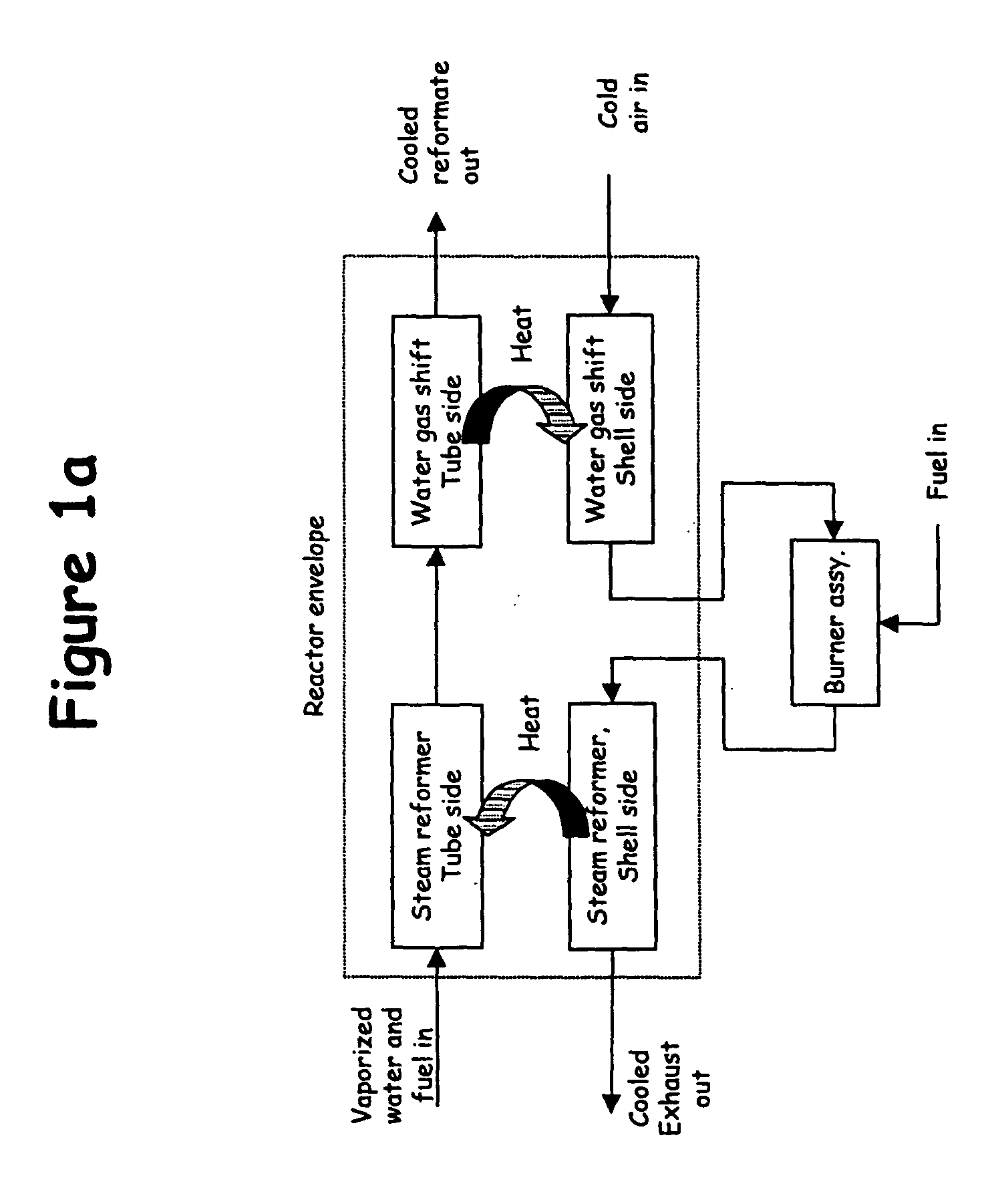
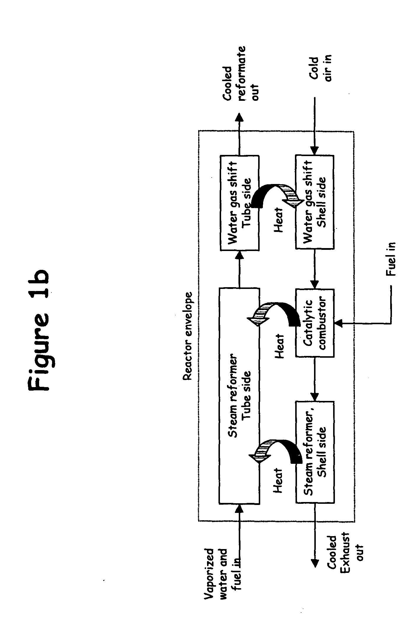
This approach, however, undesirably retains the multiple connections and extensive plumbing characteristic of the unit process approach.
Moreover, because of its complicated packaging, the assembly of the Corrigan system undesirably presents a significant challenge.
These connections once again present the same drawbacks found in unit process reactor systems.

