Synthesis of carbon nanotubes by making use of microwave plasma torch

a technology of microwave plasma and carbon nanotubes, which is applied in the field of microwave plasma apparatus and a method for synthesis of carbon nanotubes using the microwave plasma torch, can solve the problems of low yield, low overall energy efficiency, and low product purity, and achieve the effect of enhancing the electric field strength of microwave radiation

Inactive Publication Date: 2005-07-28
UHM HAN S
View PDF3 Cites 93 Cited by
  • Summary
  • Abstract
  • Description
  • Claims
  • Application Information

AI Technical Summary

Benefits of technology

[0014] It is therefore an important object of the present invention to enhance the electric field strength of the microwave radiation in order to achieve dissociation and ionization of synthesis materials in a carrier gas by exposure to a plasma torch generated by concentration of the microwave on a small spot.
[0015

Problems solved by technology

This method produces carbon nanotubes with a high crystallinity but the purity of the product may be low due to the instability of the arc and due to the non-uniformity of the growth conditions.
In spite of motorized insertion of electrodes, this approach is essentially a batch or semi-auto process yielding only a few grams of material per run, with no prospect of improvement.
This method can produce high quality material but the yields and overall energy efficiency are low.
Non-uniform ablation of the target means that this approach must be run as a batch process.
Moreover, excess amorphous carbon lumps are produced along with carbon nanotubes, and thus they need complicated purification processes.
However, filling pores of the substrate with a metal catalyst is

Method used


Image

  • Synthesis of carbon nanotubes by making use of microwave plasma torch
  • Synthesis of carbon nanotubes by making use of microwave plasma torch
  • Synthesis of carbon nanotubes by making use of microwave plasma torch

Examples


example 1

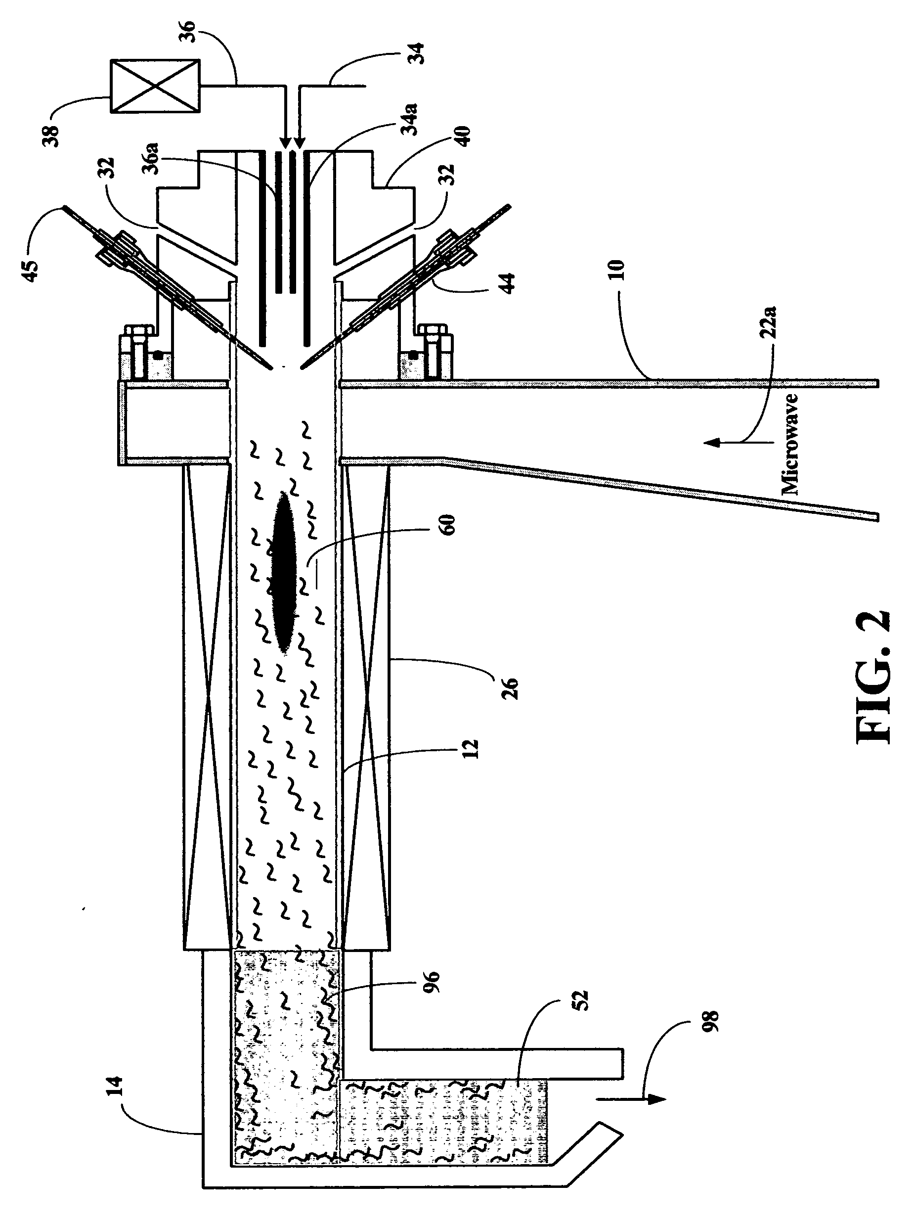
[0033] The apparatus used is shown in FIG. 2. Carbon nanotubes with the average diameter less than 80 nm and the average length of 1.5 micrometer were produced using argon as the swirl or diluent gas, acetylene as the carbon-containing gas, and iron pentacarbonyl as the transition metal precursor, which was carried by argon gas. The swirl gas flow rate was 15 liters per minute (lpm), that of acetylene was 100 standard cubic centimeters per minute (sccm), and that of the catalyst carrier gas was 50 sccm. Then the microwave forward power was 1.6 kW. The discharge tube of 30 mm diameter was used and the furnace length was 55 cm. The collector system and the furnace was maintained at 25° C. and 650˜700° C., respectively.

example 2

[0034] The apparatus used is shown in FIG. 2. Carbon nanotubes with the average diameter less than 100 nm and the average length of 1 micrometer were produced using argon as the swirl or diluent gas, hexane as the carbon-containing gas, and iron pentacarbonyl as the transition metal precursor, which was carried by hexane gas. The swirl gas flow rate was 5 lpm and that of hexane was 1000 sccm. Then the microwave forward power was 1.2 kW. The discharge tube of 26 mm diameter was used and the furnace length was 55 cm. The collector system and the furnace was maintained at 25° C. and 650˜700 ° C., respectively.

example 3

[0035] The apparatus used is shown in FIG. 2. Carbon nanotubes with the average diameter less than 100 nm and the average length of 1.5 micrometer were produced using nitrogen as the swirl or diluent gas, acetylene as the carbon-containing gas, and iron pentacarbonyl as the transition metal precursor, which was carried by argon gas. The swirl gas flow rate was 10 lpm and that of acetylene was 100 sccm, and that of the catalyst carrier gas was 50 sccm. Then the microwave forward power was 1.6 kW. The discharge tube of 30 mm diameter was used and the furnace length was 55 cm. The collector system and the furnace was maintained at 25° C. and 750˜800° C., respectively.


PUM


Abstract

The present invention relates to a synthesis method of carbon nanotubes, and more particularly to an apparatus for a mass synthesis of carbon nanotubes in gas phase using an atmospheric-pressure microwave plasma torch. The method and apparatus is described for the continuous production of carbon nanotubes by making use of a microwave plasma torch operated at a frequency of 2.45 GHz, by introducing a transition metal catalyst precursor and a carbon containing gas into the microwave plasma torch to produce atomized catalyst metal and to decompose the carbon containing gas, by passing the resulting gaseous mixtures through a furnace, and by quenching rapidly and collecting the products so formed at the exit of the furnace. The resultant products are the carbon nanotubes.

Description

REFERENCE CITED: U.S. PATENT DOCUMENTS [0001]5,137,701August 1992Mundt5,468,356November 1995Uhm5,505,909April 1996Dummersdorf et al5,830,328November 1998Uhm6,620,394September 2003Uhm et alFIELD OF THE INVENTION [0002] The present invention relates generally to a microwave plasma apparatus and a method for synthesis of carbon nanotubes using the microwave plasma torch, and more particularly a microwave plasma synthesis apparatus, which synthesizes continuously a large amount of carbon nanotubes in gas phase. The synthesized carbon nanotubes have an average diameter of 100 nm or less. BACKGROUND OF THE INVENTION [0003] Carbon nanotubes were first introduced to the scientific community by Sumio lijima through a paper entitled “Helical microtubles of graphitic carbon”, Nature, vol. 354, Nov. 7, 1991, pp. 56-58. According to the paper, it was shown that a material containing carbon nanotubes of about 15% could be produced by arc discharge between graphite rods. Since the first discovery ...

Claims


Application Information

Patent Timeline
IPC IPC(8): B01J19/08B01J19/12B01J19/26C01B31/02H05B6/80H05H1/30
CPCB01J19/088H05H1/30B01J19/26B01J2219/0809B01J2219/083B01J2219/0841B01J2219/0869B01J2219/0871B01J2219/0883B01J2219/0892B01J2219/0898B82Y10/00B82Y30/00B82Y40/00C01B31/0233C01B2202/02C01B2202/34C01B2202/36H05B6/806B01J19/126C01B32/162
Inventor UHM, HAN SUPHONG, YONG C.
Owner UHM HAN S
Why Eureka
Try Eureka