Potentiometric dna microarray, process for producing the same and method of analyzing nucleic acid

Inactive Publication Date: 2005-08-04
HITACHI HIGH-TECH CORP
View PDF1 Cites 42 Cited by
  • Summary
  • Abstract
  • Description
  • Claims
  • Application Information

AI Technical Summary

Benefits of technology

[0016] The process for producing the potentiometric DNA microarray according to one aspect of the present invention comprises the steps of: forming a silicon film on a first surface of the insulating substrate; dividing the silicon film into a plurality of silicon film formation areas by patterning of the silicon film; forming a plurality of pn junctions working as source and drain regions of the field effect transistors, a heater, and a temperature sensor, respectively, in each of the silicon film formation areas; carrying out wiring for signal from the source and drain regions with the region between the source and drain regions serving as a channel; and immobilizing nucleic acid probes directly or via a carrier at the sites corresponding to the channels of the field effect transistors on a second surface opposite to the surface where the silicon film is formed on the insulating substrate.
[0017] The

Problems solved by technology

Since the majority of the present DNA microarrays utilize detection by fluorescence as the basic principle, a laser or a complex optical system is required for them, and the system becomes larger in size and expensive.
Even if these DNA microarrays may be used repeatedly by washing, their use is limited to at most two to three times, thus giving rise to a major problem of the running cost in analyzing many samples and in the fields of gene diagnosis to test a large number of samples and the like.
Particularly in the field of medicine, it is difficult for an expensive test to come into wide use in view of cost containment of medical expenses.
It ut

Method used


Image

  • Potentiometric dna microarray, process for producing the same and method of analyzing nucleic acid
  • Potentiometric dna microarray, process for producing the same and method of analyzing nucleic acid
  • Potentiometric dna microarray, process for producing the same and method of analyzing nucleic acid

Examples


example 1

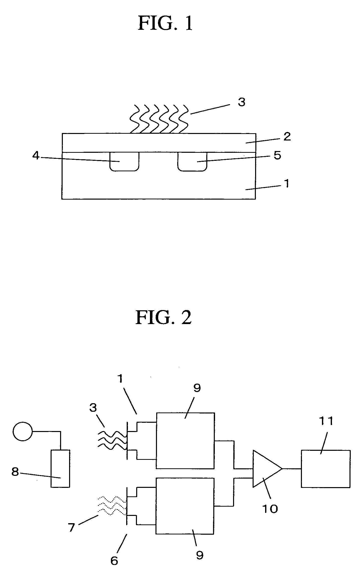
[0035]FIG. 1 is a cross sectional schematic drawing to explain an example of an electric field effect transistor (FET) for gene detection according to the present invention.

[0036] It is configured such that a nucleic acid probe 3 is immobilized on the surface of a gate insulator 2 of an insulated gate FET 1. For the nucleic acid probe is used an oligonucleotide, cDNA, or DNA fragment branched in the middle, each generally composed of 300 nucleotides or less and capable of hybridizing with a target gene to be measured under appropriate conditions. In the case of an oligonucleotide, it is preferably a nucleic acid fragment with a length of 80 bases or less. For the gate insulator, a material such as silicon dioxide (SiO2), silicon nitride (SiN), aluminum oxide (Al2O3), or tantalum oxide (Ta2O5) is used alone or in combination, and generally a bilayer structure in which silicon nitride (SiN), aluminum oxide (Al2O3), and tantalum oxide (Ta2O5) are layered on top of silicon dioxide (SiO...

example 2

[0040]FIG. 2 is a construction example to show a genetic testing system with the field effect transistor for detection of gene (Genetic FET) shown in FIG. 1.

[0041] This genetic testing system is provided with a reference FET 6 in addition to the Genetic FET 1 shown in FIG. 1, and a differential measurement between the Genetic FET and the reference FET is carried out. The nucleic acid probe 3 having the base sequence complementary to the target gene in a sample is immobilized on the surface of the gate insulator of the Genetic FET 1. On the other hand, a nucleic acid probe 7 having a base sequence that is different from the base sequence complementary to the target gene is immobilized on the surface of the gate insulator of the reference FET 6.

[0042] Such a differential measurement allows to accurately detect only the output change caused by the hybridization of the target gene and the nucleic acid probe by compensating for an output change occurring from changes in ambient tempera...

example 3

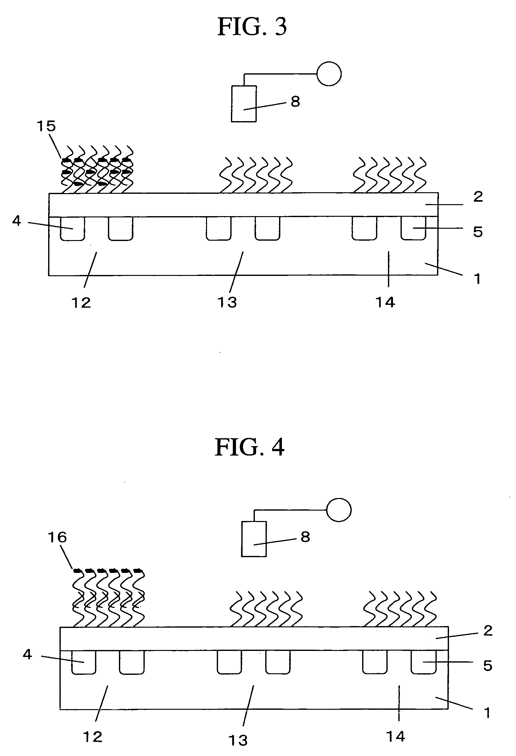
[0044]FIG. 3 is an explanatory drawing of a measurement system of the DNA microarray of the present invention in combination with an intercalator. In the illustrated example of the DNA microarray, three Genetic FETs 12 to 14 are integrated. The first FET 12 is used as a Genetic FET to detect a first target gene, the second FET 13 is used as a Genetic FET to detect a second target gene, and the third FET 14 is used as the reference FET. Nucleic acid probes having base sequences complementary to the first and second genes are immobilized on the gate insulators of the first and second FETs, respectively. A nucleic acid probe having a base sequence that is different from the base sequences complementary to the first and second genes is immobilized on the surface of the gate insulator of the reference FET.

[0045]FIG. 3 depicts a state in which a sample solution containing only the first gene is introduced to the integrated DNA microarray and hybridized with the target gene, followed by t...


PUM

PropertyMeasurementUnit
Densityaaaaaaaaaa

Abstract

A DNA microarray system whereby measurement can be performed at a low running cost, a low price and yet a high accuracy. A nucleic acid probe (3) is immobilized on the surface of a gate insulator of an electric field effect transistor and then hybridized with a target gene on the surface of the gate insulator. A change in the surface electric charge density thus arising is detected by using the electric effect.

Description

TECHNICAL FIELD [0001] The present invention relates to biotechnology in such field as genetic diagnosis, sequence analysis of DNA, or analysis of single nucleotide polymorphism, particularly to technology in the field of genetic testing and more specifically, to potentiometric DNA microarray capable of simultaneously analyzing a plurality of different nucleic acids with high accuracy, a process for producing the microarray and a method of analyzing nucleic acids. BACKGROUND ART [0002] Rapid progress has been made in the projects of genome nucleotide sequence analysis for various living organisms including the human genome project, and enormous amounts of information on the nucleotide sequence are being accumulated. At present, the entire nucleotide sequence of the human genome is being determined. From now on, elucidation of gene functions in vivo seems likely to promote dramatic developments of gene-related technology in a wide range of fields including diagnosis of various diseas...

Claims


Application Information

Patent Timeline
IPC IPC(8): B01J19/00B01L3/00C12M1/00C12N15/09C12Q1/68C40B40/06G01N27/414H01L29/06H01L29/66
CPCB01J19/0046G01N27/4145B01J2219/00585B01J2219/00596B01J2219/00608B01J2219/00612B01J2219/00621B01J2219/00626B01J2219/00637B01J2219/00653B01J2219/00659B01J2219/00722B01L3/5085C12Q1/6825C12Q1/6837C40B40/06B01J2219/00529C12Q2565/501C12Q2565/607
Inventor MIYAHARA, YUJIYASUDA, KENJIHATTORI, KUMIKO
Owner HITACHI HIGH-TECH CORP
Why Eureka
Try Eureka