System and method for treating a flue gas stream

a flue gas stream and system technology, applied in the direction of lithium compounds, separation processes, alkali metal carbonates, etc., can solve the problems of inability to meet the requirements of slag blowing,

Pending Publication Date: 2005-09-15
AMERICAN ELECTRIC POWER CO INC
View PDF18 Cites 45 Cited by
  • Summary
  • Abstract
  • Description
  • Claims
  • Application Information

AI Technical Summary

Benefits of technology

[0014] The present invention is a system and method for treating a flue gas stream to remove strong acid compounds selected from the group consisting of hydrofluoric acid (“HF”), hydrochloric acid (HCl”), sulfuric acid (“H2SO4”), and sulfur trioxide (SO3) through the injection of a sodium sorbent selected from the group consisting of sodium sesquicarbonate, sodium carbonate-bicarbonate, trona ore, mechanically refined trona ore, and trona into the flue gas stream, calcining substantially all of the sodium sorbent in the presence of the flue gas stream to form a soda ash, reacting the soda ash with at least one strong acid compound in the flue gas stream to form a sodium based by-product, conditioning the particulate matter in the flue gas stream with the sodium based by-product causing a decrease in the volumetric resistivity of the particulate matter, and removing the particulate matter and the remaining sodium based by-product from the flue gas stream in a particulate collector.

Problems solved by technology

Although each of these methods is successful in reducing SO3 concentrations in the flue gas, they each have side effects that negatively impact combustion furnace operation.
This can often lead to unacceptable operating conditions, such as clinkers, or results in a need to periodically cut load for additional slag blowing.
Liquid injection into the flue gas stream can result in large accumulations of ash deposits in the ducts and other negative impacts on the generating unit, such as corrosion to the duct, expansion joints, or structural members internal to the duct.
While treating the flue gas stream through the injection of sodium based compounds such as sodium carbonate, sodium bicarbonate, or trona into has been known for several years (See for example U.S. Pat. No. 4,559,211) these efforts have largely proved unsatisfactory because they (1) failed to take into account the effect that injecting a sodium based compound would have on particulate matter resistivity, and (2) focused on removing primarily SO2 and thus proved unable to compete economically with more efficient SO2 removal methods.
Ash with resistivity below this range may easily lose their charge and become re-entrained.
Ash with resistivity above this range do not readily accept an electrical charge, and are therefore, more difficult to capture.
When magnesium or calcium (lime) sorbents are injected for SO3 removal, these elements increase fly ash resistivity and, at sufficiently high injection rates, will negatively impact the performance of the particulate collector.
The combination of low SO3 levels due to mitigation efforts and increasing magnesium and calcium levels from the mitigation systems work together to raise fly ash resistivity, and can significantly reduce the efficiency of the particulate collector.
The gradual degradation of collection efficiency during dry lime injection is especially noticeable.
As a result, using either magnesium hydroxide or lime sorbent injection for SO3 mitigation in not often practical due to the undesirable increase in fly ash resistivity.
Many times, however, increasing the sodium content in the combustion furnace has several negative side effects including increased combustion furnace slagging, fouling, and corrosion.
In addition to the foregoing precipitator problems, injecting calcium based sorbents, such as lime into a flue gas stream that is significantly above the water saturation temperature will lower the sorbent utilization relative to injecting the lime at or near flue gas saturation temperatures.

Method used


Image

  • System and method for treating a flue gas stream
  • System and method for treating a flue gas stream
  • System and method for treating a flue gas stream

Examples


Embodiment Construction

)

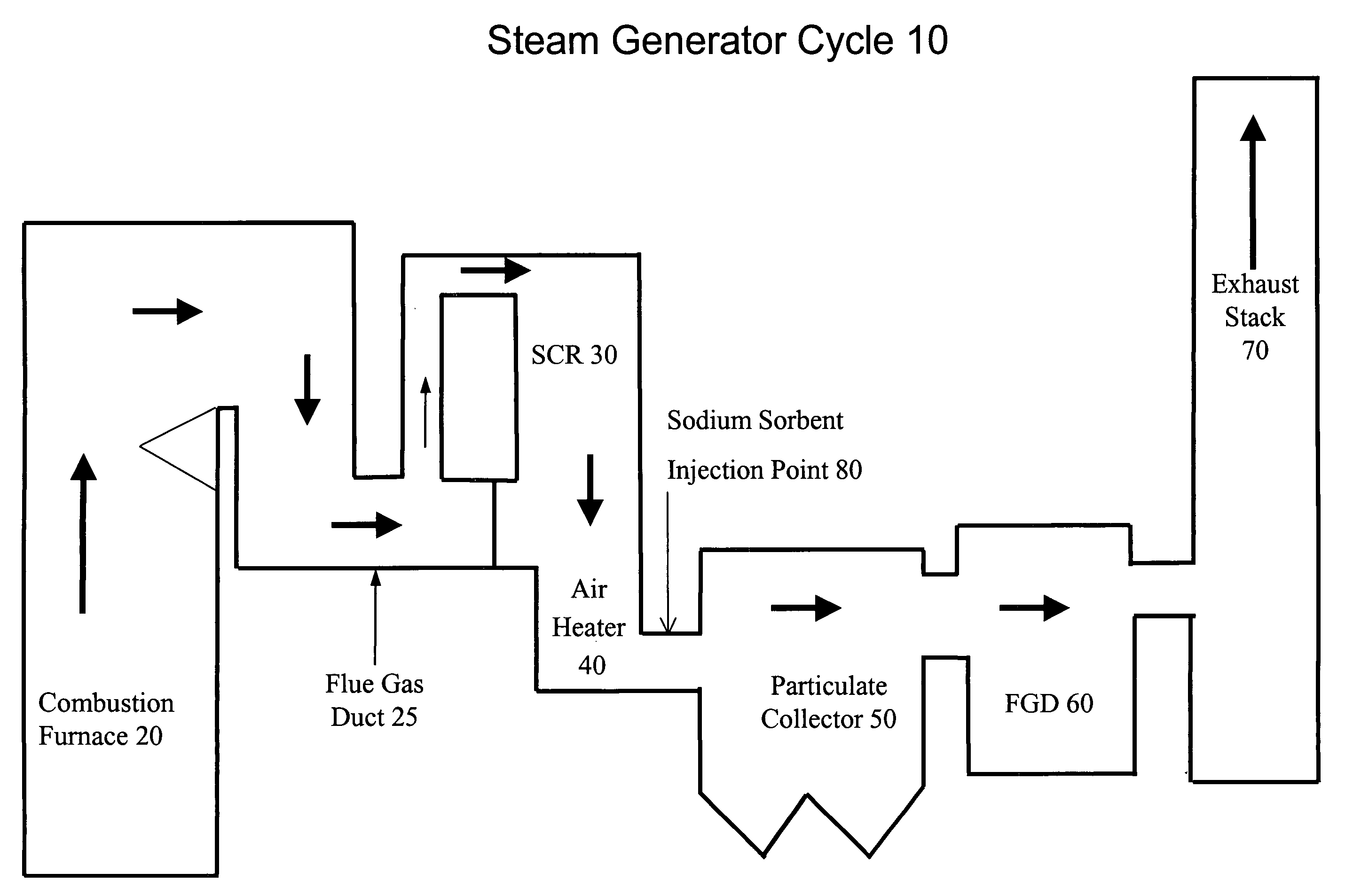
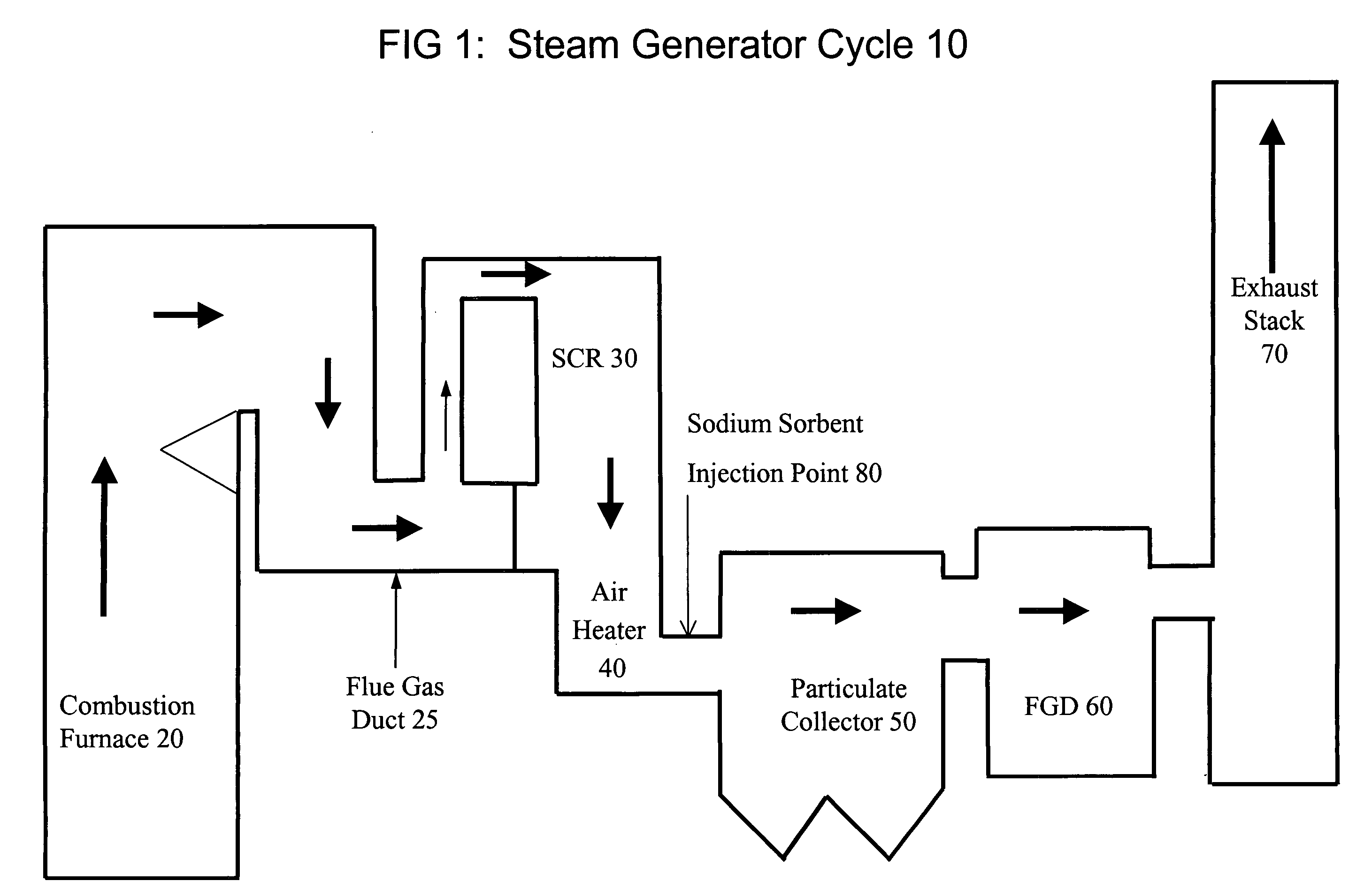
[0045] Referring now to FIG. 1, shown is a general representation 10 of a steam generator cycle of the type typically utilized in electric power generation applications. A carbonaceous fossil fuel is combusted in the presence of air in combustion furnace 20 releasing heat that is absorbed by water and steam circulating around and within the zone of combustion. In addition to the heat that is released, a flue gas stream is formed comprising water vapor, particulate matter such as fly ash, and the gaseous by-products of combustion including oxides of sulfur (SOx) and oxides of nitrogen (NOx), the levels of which must generally be reduced, in order to meet clean air standards, before the flue gas stream is discharged to the atmosphere. The flue gas stream exits combustion furnace 20 through at least one flue gas duct 25 and is directed to the inlet of selective catalytic reduction (SCR) reactor 30. The flue gas stream exits SCR reactor 30 and is directed to the inlet of air heater 40,...


PUM

PropertyMeasurementUnit
temperaturesaaaaaaaaaa
particle sizeaaaaaaaaaa
temperatureaaaaaaaaaa

Abstract

The present invention is a system and method for treating a flue gas stream to remove strong acid compounds selected from the group consisting of hydrofluoric acid (HF), hydrochloric acid (HCl), sulfuric acid (H2SO4), and sulfur trioxide (SO3) by injecting a sodium sorbent selected from the group consisting of sodium sesquicarbonate, sodium carbonate-bicarbonate, trona ore, mechanically refined trona ore, and trona into the flue gas stream, calcining substantially all of the sodium sorbent in the presence of the flue gas stream to form a soda ash, reducing the concentration of the at least one strong acid compound in the flue gas stream by reacting the at least one strong acid compound with the soda ash to form a sodium based by-product; and changing the chemistry of the flue gas stream to reduce the overall average resistivity of the particulate matter.

Description

[0001] The present application claims the benefit of U.S. Provisional Patent Application 60 / 552,908 filed Mar. 12, 2004.BACKGROUND OF THE INVENTION [0002] The system and method of the present invention relates generally to a method for treating a flue gas stream to reduce the concentration of strong acid compounds in the flue gas stream while effecting a change in the volumetric and surface resistivity of particulate matter entrained in the flue gas stream, and particularly to a method for removing strong acid compounds from a flue gas stream while effecting a change in the volumetric and surface resistivity of particulate matter entrained in the flue gas stream wherein the flue gas stream is a by-product of the combustion of a carbonaceous fuel in a combustion furnace, and more particularly to a method of injecting a sodium based sorbent into a flue gas stream resulting from the combustion of a carbonaceous fuel in a combustion furnace wherein the sodium based sorbent removes sulfu...

Claims


Application Information

Patent Timeline
Patent Type & Authority Applications(United States)
IPC IPC(8): B01D53/40
CPCB01D53/40B01D2257/2045Y02C20/30B01D2257/302B01D2257/504B01D2257/2047
Inventor RITZENTHALER, DOUGLAS P.
Owner AMERICAN ELECTRIC POWER CO INC
Why Eureka
Try Eureka