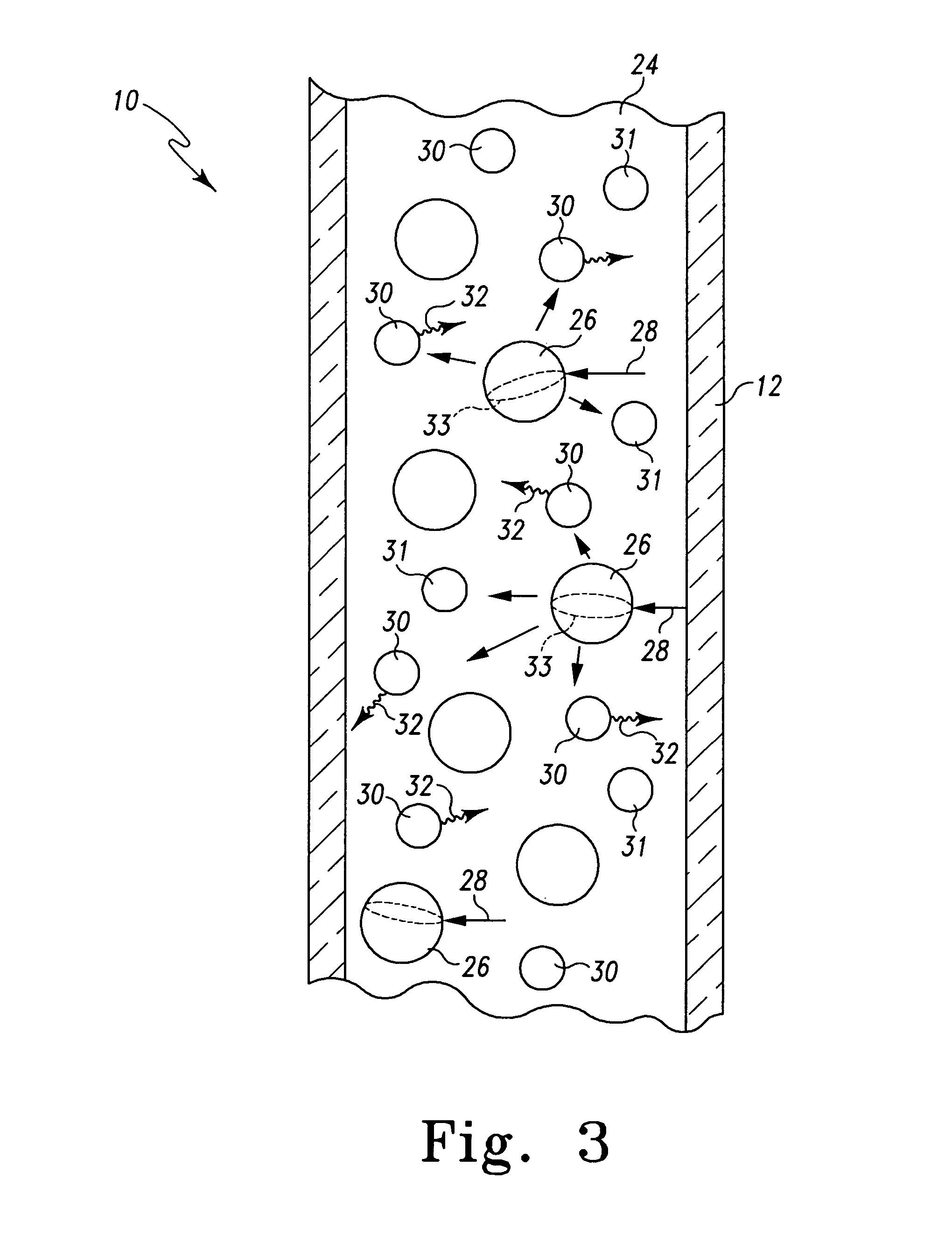
[0013] The present invention uses the properties of particles within a high-Q microcavity
capillary column to achieve an observed optical enhancement that is multiplicative rather than additive of the two processes. The capillary columns of the present invention should generally have a wall thickness on the order of or less than 1 mm. The
dielectric microparticles can be in the form of
porous glass particles, silica particles,
polystyrene or
carboxylate microspheres, which can include surface islets of coinage metals that enhance
light scattering and SERS interaction with any materials carried by the fluid buffers within the capillary column. The
dielectric microparticles can be those developed for use as conventional chromatographic
solid supports, or
flow cytometry particles, and are available uncoated or derivatized with reactive functional groups such as supports for affinity,
ion exchange, and
size exclusion chromatography. The kinds of nanoparticles that can be used in the present invention include spherical and non-spherical particles including a coinage
metal component with average diameters in the 1 nm to 500 nm range, either in monomeric form or aggregated clusters. The dielectric microparticles can be used, for example, as
enzyme reactors,
immunosorbents, biosensors, and for
solid phase synthesis. Since the nanoparticles and the dielectric microparticles can also produce large optical scattering, they can facilitate the excitation of optical MDR
modes within the glass walls of the capillary column. These
resonance modes greatly enhance the
Raman scattering intensity from proteins and other organic target molecules and compounds in the column. Such optically resonant columns including
optically active dielectric microparticles and / or
metal component nanoparticles can achieve ultra-low threshold micro-analysis, including
spectroscopy of nano-molar, pico-molar, and even
femto-molar concentrations of target molecules, and potentially even single molecules.
[0015] The
processing of the collected data can involve any number of conventional
signal processing techniques that are well known to those skilled in the art. For example, the data can initially be cleaned to remove spectral artifacts such as
fluorescence interference and cosmic spikes. In particular,
fluorescence background can be reduced with
wavelet transformation or derivative methods, and cosmic spikes can be eliminated with Upper Bound Spectra (UBS) or UBS data—matrix (UBS-DM) methods depending on the amount of data gathered during the measurement. Next, it is often desirable to enhance the performance of several commonly used classification algorithms especially when the sample size is limited compared with the number of measurement features. This is achieved by
feature selection and / or augmentation. Next the enhanced and / or feature selected portion of the data is subjected to Principal Components Analysis (PCA),
Linear Discriminant Analysis (LDA), Quadratic
Discriminant Analysis (QDA), Regularized
Discriminant Analysis (RDA), Partial
Least Squares (PLS) analysis, and combinations thereof with these or other recognized methods to better classify and correlate the observed data with known standards. With the Raman spectra collected from the column at various times and locations, Multivariate Curve Resolution (MCR) methods can be implemented to obtain the pure component spectra and thus derive a chromatogram for individual component under consideration. Then
classification methods are applied to the pure component spectra to identify the
protein or other organic molecule under investigation.
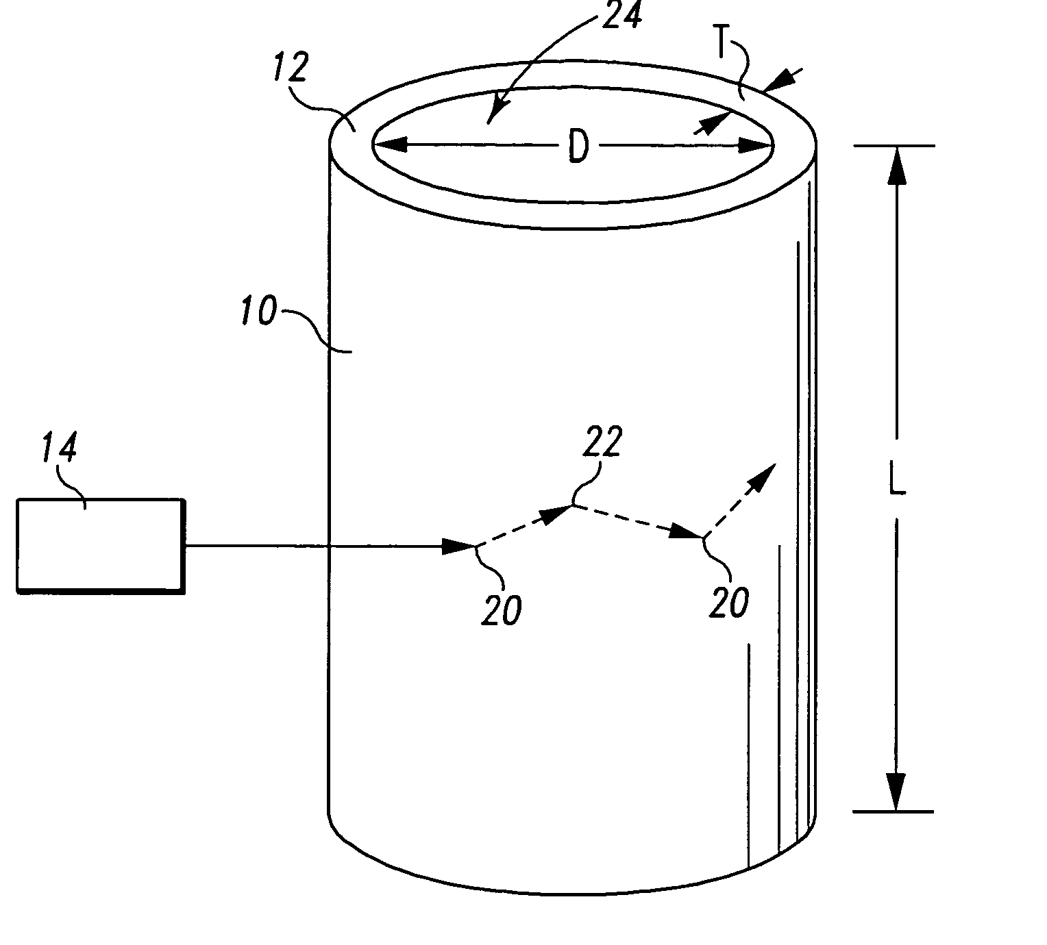
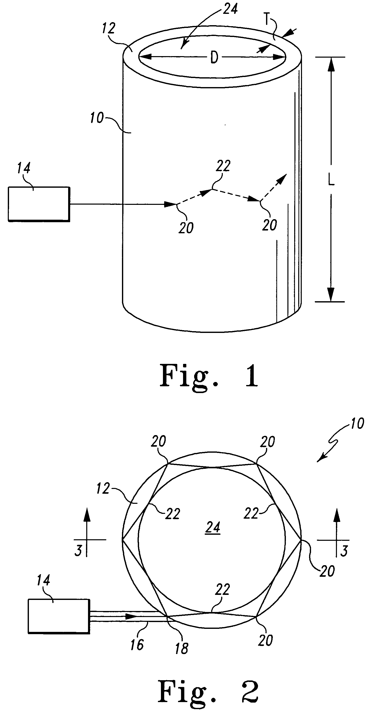
[0017] One feature of the present invention is the utilization of a capillary column having a wall dimensioned to permit resonant
modes of the introduced
optical energy to exist within the column wall and to couple resonant modes with a medium inside the column. This feature has the
advantage of significantly enhancing the
optical coupling between the introduced
optical energy and the various materials present within the column, including at least the
target protein or other organic molecule as well as the optically interactive dielectric microparticles that are within the column. The plurality of dielectric microparticles facilitates in turn a
coupling of the resonant modes with the target medium.
[0018] Another feature of the present invention is that the flow of the
target protein or other organic molecule through the length of the column can be achieved by any means capable of generating a migration gradient without affecting the ability to retrieve satisfactory Raman data. This feature allows for the adaptability of the structures of the present invention for Raman data gathering to a broad range of chromatographic, electrophoretic, and other proteomic processes and equipment.

