Energy efficient sorption processes and systems

a technology of energy-efficient sorption and process, applied in the direction of solar heat devices, lighting and heating apparatus, furnace types, etc., can solve the problems of reducing the efficacy of regeneration process, ld transport along with air stream, etc., to increase heat and/or mass transfer, increase interfacial area, and reduce temperature

Inactive Publication Date: 2005-12-01
INDIAN INST OF TECH
View PDF5 Cites 48 Cited by
  • Summary
  • Abstract
  • Description
  • Claims
  • Application Information

AI Technical Summary

Benefits of technology

[0088] The main object of the present invention is to provide a novel energy efficient multi-stage regeneration process, for regenerating liquid desiccant (LD), with application of rotating contacting disks to provide intimate contact between LD and vapour/gas to enhance the interfacial area between them for increased heat and/or mass transfer, without problems of carryover of liquid in to the vapour/gas stream or flooding having the provision to h...

Problems solved by technology

The main problem associated in this regeneration process is carryover of LD along with air stream.
Requirement of minimum irrigation rate and limitations of flooding in packed towers complicates the design or reduces the efficacy of the regeneration process.
Also large power is required to circulate air/gas through packed bed.
However, there is a relatively high pumping cost for spraying the LD.
The tendency for carry over of liquid by the air/gas is considerable in the spray towers and mist eliminators will almost always be necessary leading to increase the air/gas side pressure drop.
The disadvantage of the regeneration process is that the system is not operative during non-solar hours.
The regeneration process in a simple boiler is not energy efficient since the latent heat of the vapour generated is not recycled.
This increases the electrical power consumption.
However, maintaining vacuum in low-pressure boiler increases the electrical power consumption.
Costly components are required for high-pressure boilers and an issue of safety becomes more complex.
The single stage regeneration process is exergetically less efficient.
Two heat exchangers are used to deliver the latent heat of vapour to pre heat the LD, which is not energy efficient.
The main problem with such arrangement is corrosion of the condenser coil.
Moreover as the LD is sprayed, carryover and loss of LD to indoor and out door air streams is inevitable.
Random packings offer large specific surface but suffer from larger air/gas side pressure drop.
Such equipments need well-designed tower shells, packing supports, liquid distributors, packing restrainers, entrainment eliminators etc., which make them fairly expensive.
Minimum irrigation rate and flooding in packed towers complicates the design or reduces the efficacy of the process.
However, this patent does not address the issue of carry over of liquid along with air/gas.
In U.S. Pat. Nos. 5,882,772 and 6,007,915, packing materials to increase the surface area, in packed bed towers are reported but do not comprehensively resolve all the issues as required.
However, the prior art does not teach any of the aspects of the wetting of the discs by water, their optimal sizes, etc.
This device does address the issue of proper wetting of the pad without splashing or blowing, at rotating speeds of around 2 rpm, but the cost of the rotor is high.
However, the initial cost increased to US$ 140 per kW cooling capacity (Parson, B. K., Pesaran, A. A., Bharathan, D. and Shelpuk, B.
The main problem with such arrangement is corrosion of the condenser and evaporator coils.
In this case too the carry over of LD with the process air is unavoidable as the desiccant is sprayed in the system.
In this patent problems due to the carryover of LD with air stream are not addressed
Such systems are prone to loosing the contact between the adsorbent and the heat transfer surface as the system is cycled repeatedly leading to reduced thermal conductivity over a period of time a...

Method used


Image

  • Energy efficient sorption processes and systems
  • Energy efficient sorption processes and systems
  • Energy efficient sorption processes and systems

Examples


example 1

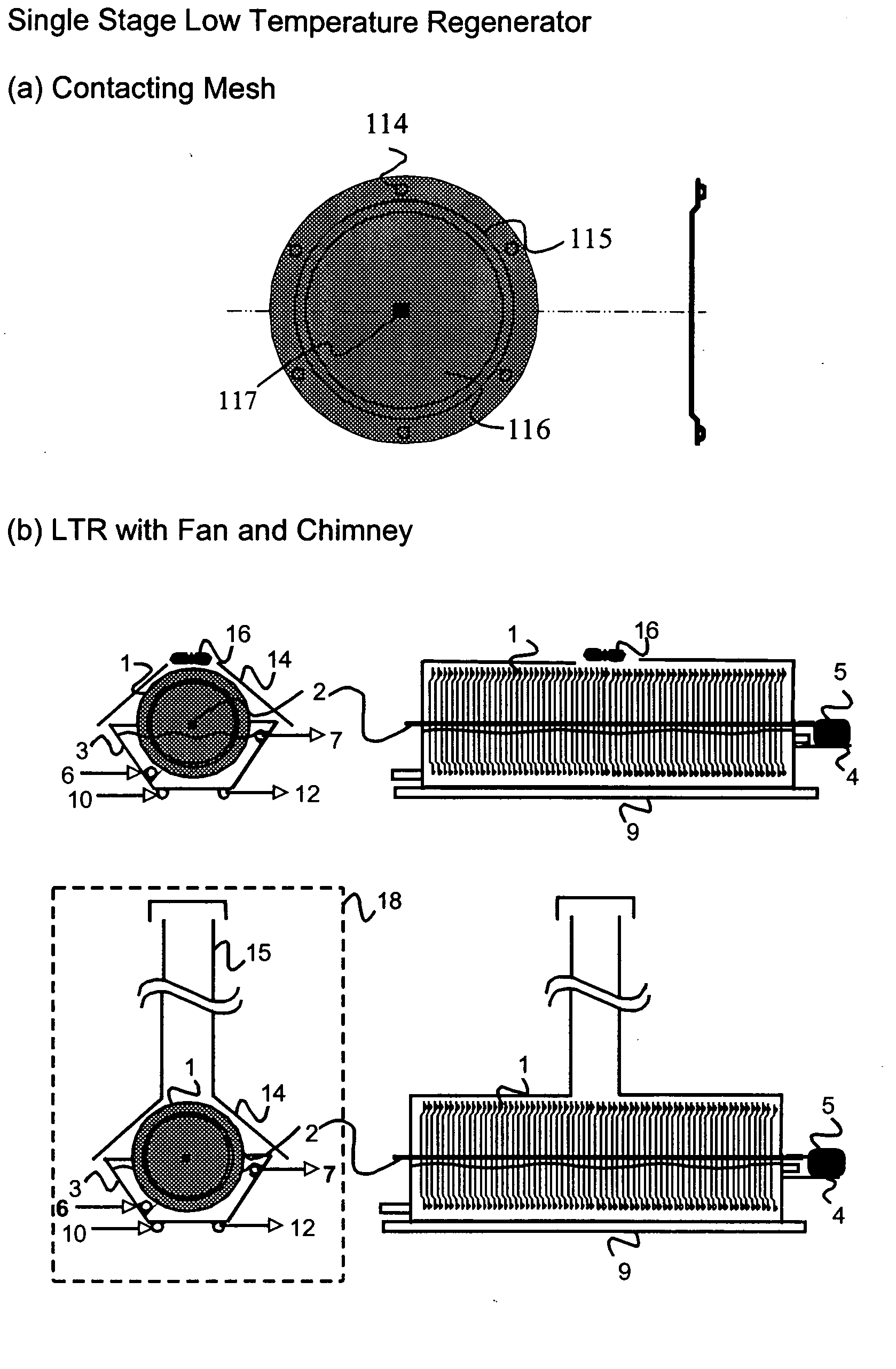
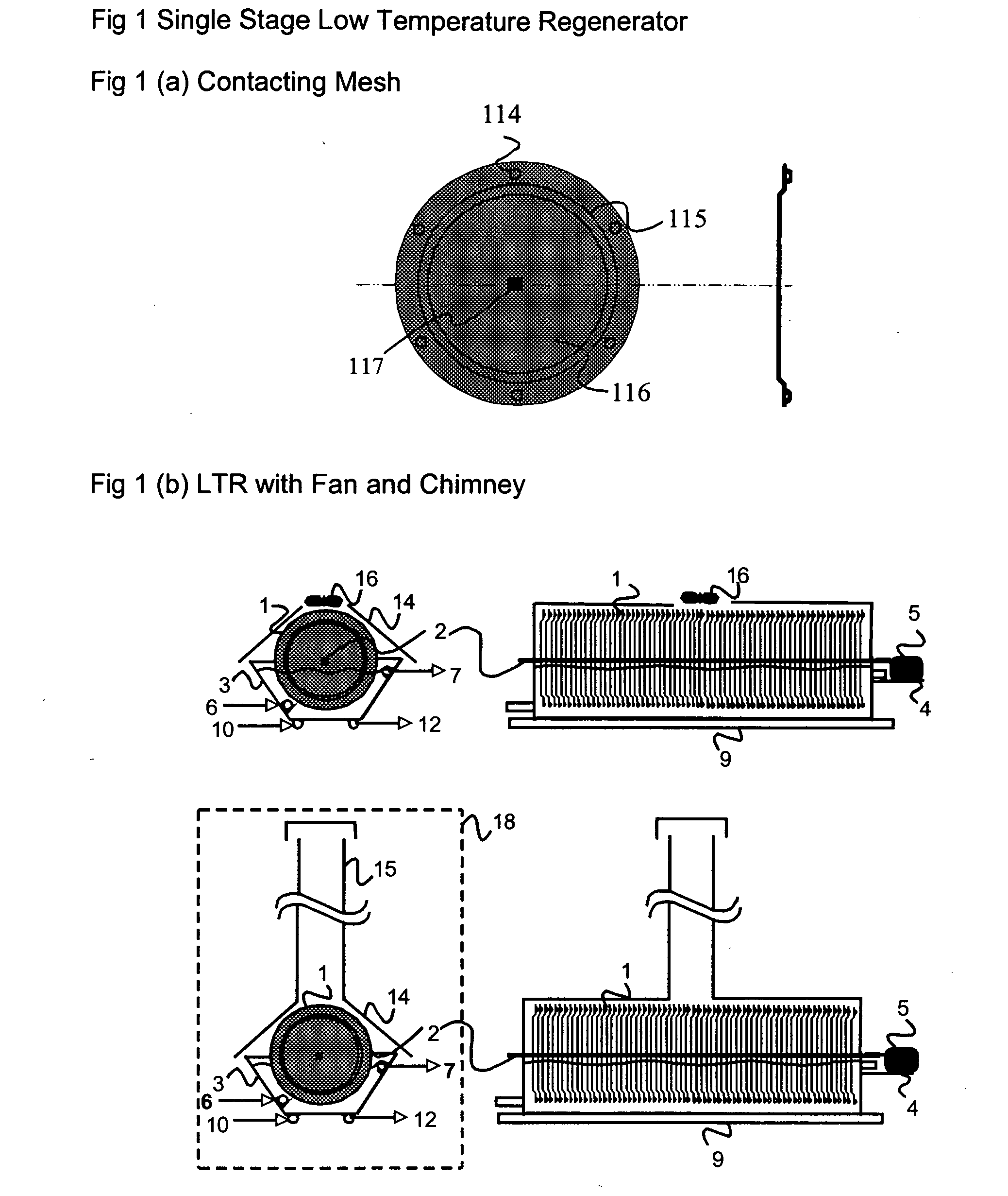
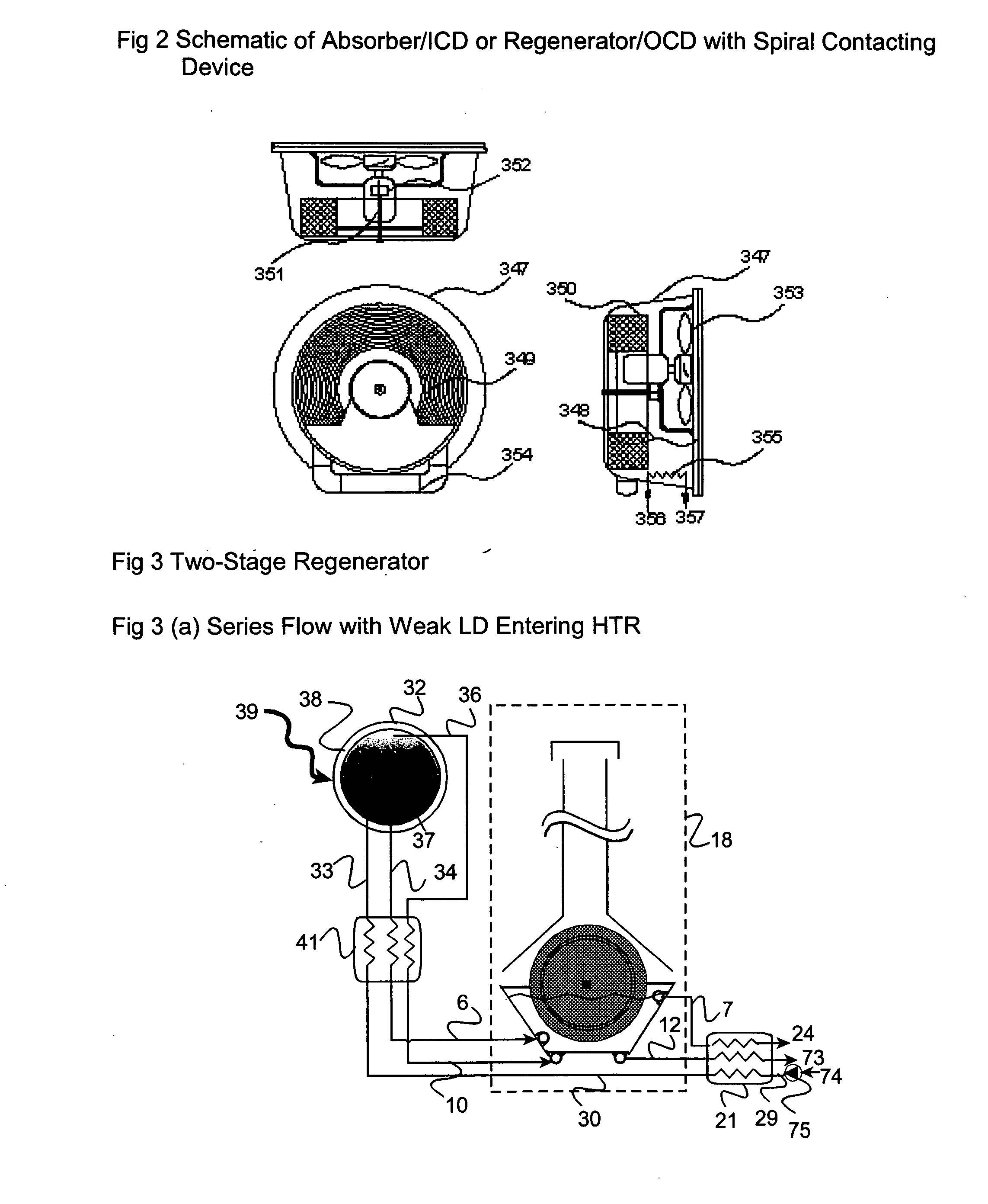
[0347] A two-stage regenerator device was fabricated and tested for regeneration of calcium chloride LD. It comprises a HTR made of aluminium rectangular channel in which electrical heaters are incorporated as heat source. LTR incorporates the aluminium disks are of 150 mm diameter, with circumferential lip and dimples as the contacting device between LD and ambient air. The disks are mounted on an aluminium shaft of diameter 9.5 mm. The disks are placed in a semi hexagonal aluminium trough 500 mm (length)×200 mm (width)×210 mm (height). It incorporates 337 m2 / m3 surface density, when maintaining 5 mm gap between the disks using plastic spacers. Contacting device is covered with a hood and a chimney of diameter 100 mm, length 1.5 m. Airflow through the contacting device is due to natural convection induced by the chimney effect. The disks are made to rotate at 5 rpm using an electric motor. Inlet and out let of LD to the trough is through 9.5 mm diameter aluminium tubes. The experim...

example 2

Humidification of Air Using Contacting Device

[0350] The contacting device was fabricated and tested for humidification of ambient air. It comprises discs made of aluminium mesh. The discs are of 150 mm diameter, with circumferential lip and dimples. The discs are mounted on an aluminium shaft of diameter 9.5 mm. The discs are placed in a semi hexagonal aluminium trough 500 mm (length)×200 mm (width)×210 mm (height). It incorporates 337 m2 / m3 surface density, when maintaining 5 mm gap between the discs using plastic spacers. Contacting device is covered with a hood and a chimney of diameter 100 mm, length 1.5 m. Airflow through the contacting device is due to natural convection induced by the chimney effect. The discs are made to rotate at 5 rpm using an electric motor. Inlet and out let of water to the trough is through 9.5 mm diameter aluminium tubes. The experimental result in Table 2 shows that the contacting device efficiency for humidification of air is as high as 98% for the ...

example 3

Results of CaCl2 Using Hybrid Cooling System

[0351] A hybrid cooling system is designed with the following specification:

a.Evaporator duty3.52kW (1 TR)b.CaCl2 solution temperaturesi.Condenser inlet45.9°C.ii.Condenser outlet49°C.iii.Evaporator inlet24.1°C.iv.Evaporator outlet20°C.c.Evaporator exit superheat5°C.d.Condenser exit sub-cooling0°C.e.Condenser temperature51°C.f.Evaporator temperature15°C.g.Compressor isentropic efficiency80%h.Hermetic compressor motor efficiency84%i.Ratio of clearance to swept volume5%

[0352] The salient features of the model are as follows: [0353] a. The model is developed for the design of a HCS with single stage VCRS [0354] b. A liquid-vapour heat exchanger / refrigerant sub-cooler may be incorporated on the refrigerant side to further improve the capacity and COP of the HCS. [0355] c. A liquid-liquid heat exchanger / solution heat exchanger is also designed on CaCl2 solution streamside for energy saving and for enhancing the overall system COP and capacity...


PUM


Abstract

The present invention relates to novel energy efficient sorption processes and systems for cooling, dehumidifying and heating using multistage liquid desiccant regenerators, or hybrid cooling systems or adsorption cooling systems involving appropriate combinations of rotating contacting devises, adsorption modules with heat transfer passages in thermal contact with the adsorption module wall and switchable heat pipes. The sorption processes of this invention help in flexible designing of compact cooling, dehumidifing, heating systems easy operability. The adsorption module of this invention leads to lower cycle times as low as 5 minutes; makes it possible to achieve high system Coefficient of Performance (COP) up to 0.9 due to reduced thermal mass; offers high specific cooling power in the range of 50 to 750 W/kg of AC; is easy to manufacture and operates at low costs. The refrigeration cum heating system of this invention with heat pipe in thermal contact with the adsorption modules increase the heat transfer rates without increasing the thermal mass leading to increase of COP and the single or multistage pressure equalisation increases the internal regeneration of heat thereby increasing the COP, reducing the cycle time resulting in increased specific cooling power (SCP), reducing the required quantity of adsorbent/refrigerant making the module compact and cost effective.

Description

RELATED APPLICATIONS [0001] This application claim priority from Indian Provisional Application Ser. Nos. (1) “Contacting Device,” 153 / MUM / 2002 filed on 19 Feb. 2002; (2) “Hybrid Cooling Systems,” 154 / MUM / 2002 filed on 19 Feb. 2002; (3) “Energy Efficient Regeneration,” 767 / MUM / 2002 filed on 23 Aug. 2002; (4) “Refrigeration cum Water Heating System,” 151 / MUM / 2002 filed on 19 Feb. 2002; (5) “Switchable Heat Pipe,” 152 / MUM / 2002 filed on 19 Feb. 2002; and (6) “Adsorption Module” 155 / MUM / 2002 filed on 19 Feb. 2002, the entire disclosures of which are hereby incorporated herein by reference.FIELD OF THE INVENTION [0002] The present invention relates to novel energy efficient sorption processes and systems for cooling, dehumidifying and heating using multistage liquid desiccant regenerators, or hybrid cooling systems or adsorption cooling systems involving appropriate combinations of rotating contacting devise, adsorption module with heat transfer passages in thermal contact with the adsor...

Claims


Application Information

Patent Timeline
IPC IPC(8): B01D53/26F24F3/14F25B17/08F25B27/00F25B27/02F25B35/04
CPCB01D53/263Y02T10/16F24F2003/144F24F2203/1004F24J2/32F25B17/08F25B27/007F25B27/02F25B35/04F25B2315/005F28D15/0266F28D15/0275F28D15/06Y02E10/44F24F3/1417F24S10/95Y02T10/12Y02A30/274Y02E10/40
Inventor RANE, MILIND V.KOTA REDDY, S. V.AGARWAL, AKHILBAJAJ, JASKARAN S.
Owner INDIAN INST OF TECH
Why Eureka
Try Eureka