Nevertheless, such optical-based modalities lack the ability to observe moderately thick three-dimensional (3D) non-transparent samples.
They can not measure vital parameters such as molecular
self diffusion and 3D flow vectors, and, for example in terms of medical tissues, many times result in inconclusive
clinical diagnosis of histological samples.
Furthermore, using optical methods, the following difficulties are encountered: it is difficult to image accurately the O2
partial pressure in specimens; it is difficult to recognize with high specificity various superoxides in the imaged sample; one can not measure a variety of image contrasts such as the spatially-resolved magnetic
resonance relaxation times (T1 and T2) and the lineshape of the
spins in the sample; and optical methods lack the possibility to correlate in-vitro with in-vivo measurements.
The main drawback of the existing NMR microscopes is their high price (in the range of $500,000 to $1,500,000, mainly due to the
superconducting magnet technology required for their operation), and the limited
image resolution they offer (>10 microns), which can not rival the <0.5 micron resolution of
optical imaging modalities.
Due to these limitations (and regardless of the many potential advantages), the full potential of magnetic
resonance microscopy cannot be readily exploited and such instruments are presently much less abundant than the optical-based microscopes in scientific and medical laboratories around the world.
Such experiments, conducted in-vivo, employ low fields of ˜10 mT at low RF frequencies (which results in relatively low spin sensitivity), so that the RF energy will penetrate deeply into the relatively large biological object.
Such high
permittivity small
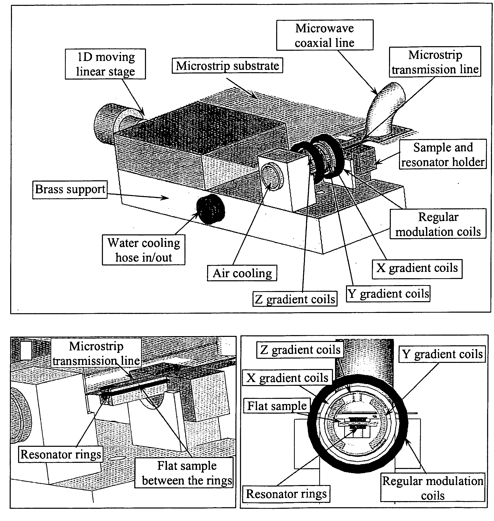
resonator structures, however, were not employed in the past as a basis for a miniature ESR imaging probe (which includes a
resonator and the imaging gradient coils).
Nevertheless all these methods can be employed only to a very limited extent when botanically and biologically-related or relatively thick samples are considered.
Thus, for example, the detection by magnetic tips as described in U.S. Pat. No. 6,683,451 suffers from low 3D sensitivity, especially when the samples are thicker than a few microns.
Furthermore, this technique requires extreme physical conditions (high vacuum and often low temperatures), and can be employed only after complicated
sample preparation.
The Hall detection and the miniature
microwave scanning probe methods also operates only on the surface, or slightly below it, and have not proven to be useful in micron resolution imaging.
A number of problems in
nuclear magnetic resonance imaging have been observed, including the need for strong magnetic fields, requiring expensive superconducting magnets, and the limited spatial resolution of images that are obtained.

