
Catalyst and method for decomposition of perfluoro-compound in waste gas

a technology of perfluorocompound and waste gas, which is applied in the direction of catalyst activation/preparation, physical/chemical process catalysts, and catalysts, etc., can solve the problems of limited commercial applications, insufficient durability of plasma generating systems, and severe corrosion of burning apparatuses, etc., to promote hydrolysis reaction, reduce decomposition rate, and high catalytic activity and durability

Inactive Publication Date: 2006-02-02
KOREA RES INST OF CHEM TECH +1
View PDF11 Cites 26 Cited by
  • Summary
  • Abstract
  • Description
  • Claims
  • Application Information

AI Technical Summary

Benefits of technology

[0016] The present invention will be described in more detail as follows. The present invention is directed for the decomposition of PFCs using a catalyst and water vapor, in which the improved catalytic activity capable of decomposing PFCs completely at a temperature of below 800° C. as well as improved catalyst durability was acquired.
[0021] In order to prevent the transformation of acidic surface of the present aluminum oxide catalyst to a dense and inert one by the exposure to the hot water vapor and HF, a variety of phosphorous (P) components can be used as a phase stabilizer or a thermal stabilizer. However, it is preferred to use phosphate compounds, which do not contain metal components, such as diammonium hydrophosphate ((NH3)2HPO4), ammoniumdihydrophosphate (NH3H2PO4) or phosphoric acid (H3PO4) for the catalytic activity and thermal durability.
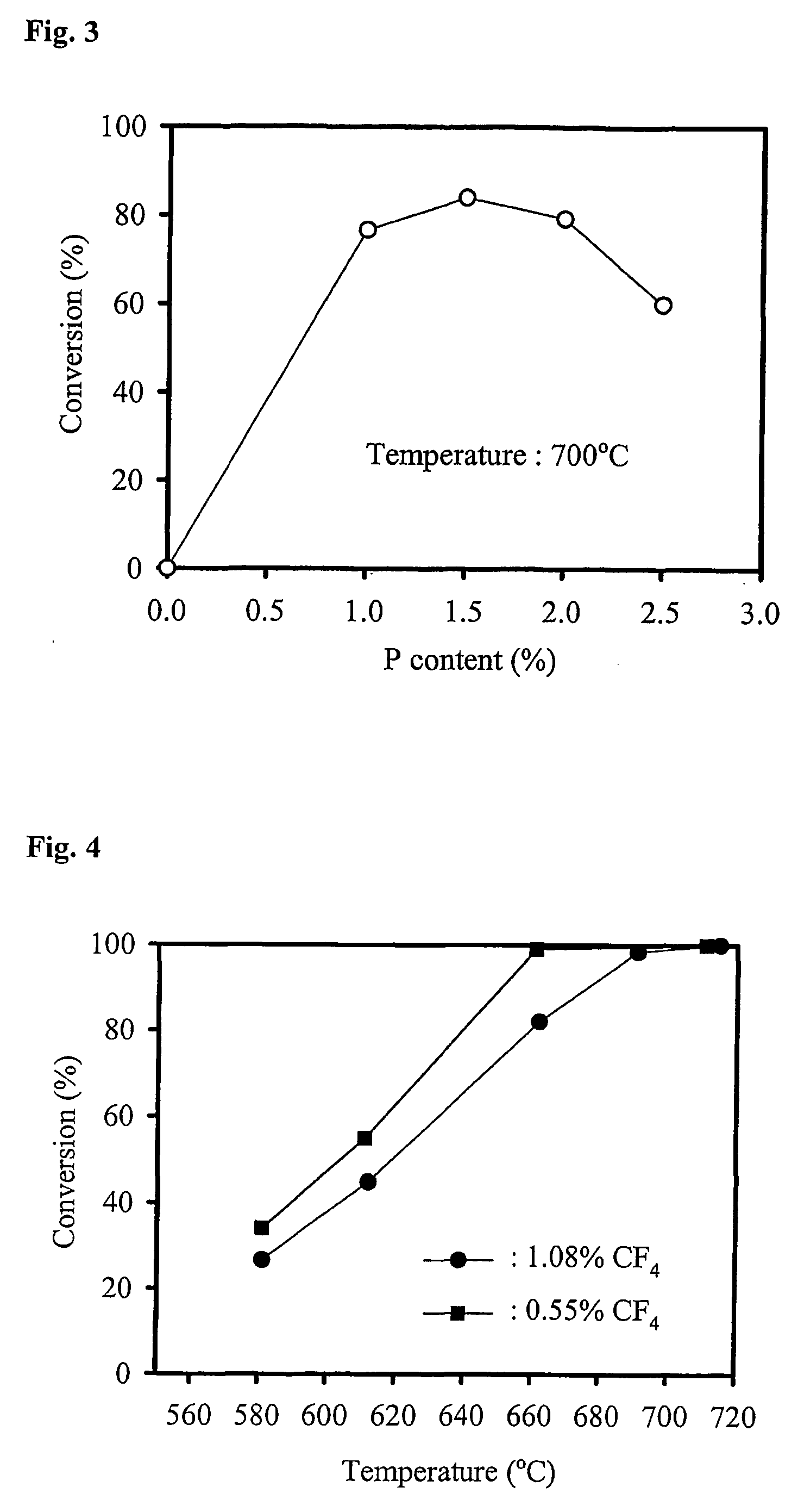
[0027] In particular, a trace amount of P component loaded on the surface of the catalyst of the present invention plays an important role for promoting the hydrolysis reaction of Scheme V as well as for a phase stabilizer of a catalyst. The role of P can be seen clearly from the result that the bare aluminum oxide without modification of P revealed the decomposition activity of PFCs only for 2 days due to the formation of aluminum fluoride (AlF3) through the reaction of aluminum oxide with HF. Unlike bare aluminum oxide, however, if the P component is loaded on the surface of aluminum oxide, the Cat.-F formed on the surface of the catalyst reacts with the —OH groups generated by the introduced P component and returned to the original state of Cat. with the production of HF, which results in no accumulation of HF on the catalyst. That is, in the presence of P component, Scheme V becomes more favorable than Scheme IV above a specific temperature and F component does not accumulate on the catalyst surface. The effect of P could be seen clearly in hydrolysis of NF3; in the case of pure aluminum oxide catalyst, as the reaction proceeded at the reaction temperature of 400-500° C., the F began to accumulate on the catalyst surface and the decomposition rate decreased gradually while only small amount of F component formed on the catalyst surface and the decomposition activity was maintained over the aluminum oxide catalyst modified with P of the present invention due to the more enhanced activity of Scheme IV than that of Scheme V.

Problems solved by technology

For the abatement of PFCs exhausted from industries, several types of treatment methods such as a) direct burning, b) plasma decomposition, c) recovery and d) catalytic decomposition have been suggested but their commercial applications are limited due to due to their own drawbacks.
It requires an extremely high temperature of above 1,400° C., which accompanies several drawbacks such as system indurability and formation of toxic by-products.
That is, due to the high temperature i) a lot of thermal Nox are formed by the reaction of nitrogen and oxygen contained in waste gas and ii) the burning apparatus are suffered severely from corrosion by the HF generated in decomposition of PFCs.
However, the radicals generated by plasma have high energy state and make the PFCs molecules decomposed randomly and unselectively, which resulted in a generation of by-products such as NOx, O3, COF2 and CO together with the desired products of CO2 and F2.
In addition, the plasma generating system does not provide sufficient durability for continuous operation.
To ensure economic feasibility, the PFCs have to be recovered in high purity and at low cost but practically it is not easy to recover the PFCs in high purity discharged irregularly in small amount in scattered places.
However, the lifetime of a catalyst has not been guaranteed enough for continuous operation in reactive HF environment.
In catalytic decomposition of PFCs, hydrogen fluoride (hereinafter referred to as HF) produced as a by-product causes severe problems for the stability of a catalyst due to its strong corrosiveness and reactivity.
That is, most of the candidate catalysts have been suffered from deactivation even though they have high initial decomposition activity.
Therefore, the catalyst has a limit for commercial application where a long lifetime of catalyst is required.
However, the lifetime of a catalyst, a most important factor to be considered in commercialization, is not guaranteed, together with complicated preparation procedure of the catalyst.

Method used


Image

  • Catalyst and method for decomposition of perfluoro-compound in waste gas
  • Catalyst and method for decomposition of perfluoro-compound in waste gas
  • Catalyst and method for decomposition of perfluoro-compound in waste gas

Examples


example i

[0043] For the preparation of aluminum oxide catalyst loaded with 2.5 mole % (Al / P=39) of P, 0.2.7 g of (NH3)2HPO4 dissolved in 35 g of distilled water was impregnated on 40 g of aluminum oxide (Al2O3) powder and then followed by oven drying at 100° C. for 10 hrs and calcining in muffle furnace at 750° C. for 10 hrs.

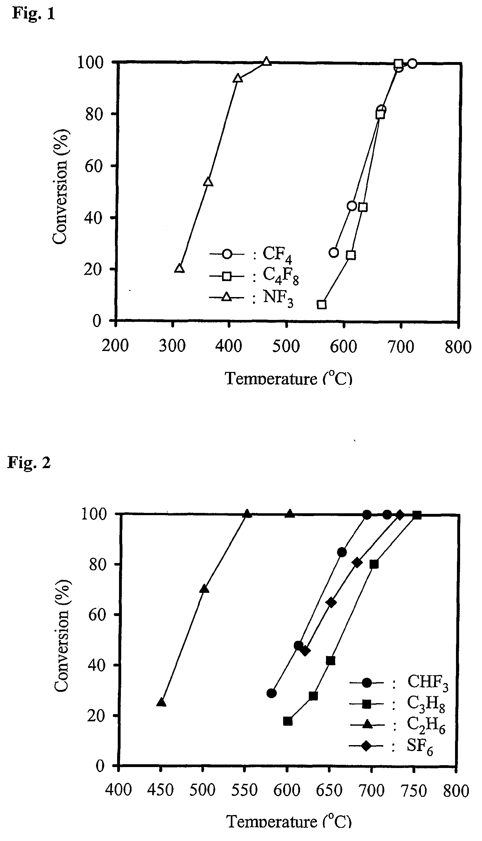
[0044] 5 g of the obtained catalyst was charged into a ¾″ Inconel tube and then PFC decomposition reaction was carried out while flowing 1.01 ml / min CF4, 2.87 mL / min O2 and 89.4 ml / min He gases, which corresponds to 1.08 vol % of CF4 anda space velocity of 1,500 h−1 except water at room temperature. 0.04 ml / min of distilled water was introduced together with gas mixture using a syringe pump. The conversion of CF4 was calculated based on the following formula 1. As shown in FIG. 1, the CF4 was decomposed into to CO2 with 100% selectivity above 690° C.

CF4 Conversion=[1−(CF4 concentration at outlet of reactor / CF4 concentration at inlet of reactor)]×100  Formula 1

Selectiv...

example ii

[0045] NF3 decomposition reaction was carried out in the same reaction condition as in Example I after loading 5 g of the catalyst prepared in Example I. Instead of CF4, 1.01 ml / min NF3, 2.87 ml / min O2 and 89.4 ml / min He gases together with 0.04 ml / min distilled water were fed to the reactor. As shown in FIG. 1, 100% of NF3 was decomposed above 400° C. Elemental analysis of the catalyst was carried out after 10 hours reaction at 500° C. using an energy dispersion x-ray analyzer (EDAX). It was found that F component did not accumulate in the catalyst even after reaction.

example iii

[0046] C4F8 decomposition reaction was carried out in the same reaction condition as in Example II after loading 5 g of the catalyst prepared in Example I. Instead of NF3, 1.08 ml / min C4F8, 2.87 ml / min O2 and 89.4 ml / min He gases together with 0.04 ml / min distilled water were fed to the reactor. As a result, it was found that 100% of C4F8 was decomposed into CO2 above 690° C. (see FIG. 1).


PUM

PropertyMeasurementUnit
Temperatureaaaaaaaaaa
Fractionaaaaaaaaaa
Concentrationaaaaaaaaaa

Abstract

The present invention relates to a catalyst for the decomposition of exhausted perfluoro-compounds (PFCs) and a catalytic decomposition method of PFCs by using the same. More particularly, the present invention relates to a PFC decomposition catalyst prepared in such a manner that a surface of aluminum oxide is loaded with phosphorous (P) component at a aluminum / phosphorous mole ratio of 10 to 100 and a decomposition method of PFCs by using the catalyst. The present catalyst can be decomposed PFCs at 100% rate exhausted from semiconductor manufacturing industry and thus prevent the release of PFCs having high global warming potential into atmosphere.

Description

TECHNICAL FIELD [0001] The present invention relates to a catalyst for decomposing perfluoro-compounds (PFCs) in waste gas and a method for decomposing perfluoro-compounds by using the same. More particularly, the present invention relates to a catalyst for decomposing PFCs prepared in such a manner that a surface of aluminum oxide is loaded with phosphorous (P) component at a mole ratio of aluminum / phosphorous ranging from 10 to 100 and a method for decomposing PFCs by using the catalyst. The catalyst of the present invention can decompose 100% of PFCs exhausted in semiconductor and LCD manufacturing processes, which can prevent the release of PFCs that causes global warming into the atmosphere. BACKGROUND ART [0002] PFCs are widely used as an etchant in semiconductor or LCD etching process and as a cleaning gas in chemical vapor deposition process. PFCs having usages as described above include CF4, CHF3, CH2F2, C2F4, C2F6, C3F6, C3F8, C4F8, C4F10, NF3, SF6 and the like. Besides in...

Claims


Application Information

Patent Timeline
IPC IPC(8): B01J27/187B01J27/14B01J27/18B01D53/86B01J27/16B01J37/02
CPCB01D53/8659Y02C20/30B01J37/0201B01J27/16B01J27/18
Inventor PARK, YONG-KIREOL, JONG JEONKIM, HEE YOUNGLEE, DONG CHAE
Owner KOREA RES INST OF CHEM TECH
Learn More