
Method of pulsed laser assisted surface modification

a technology of laser assisted surface and laser assisted coating, which is applied in the direction of vacuum evaporation coating, coating, electric heating, etc., can solve the problems of poor adhesion and composition control, long reaction time, and limited processing, and achieves improved surface properties, low processing and equipment costs, and high uniformity.

Inactive Publication Date: 2006-03-09
NANOTHERAPEUTICS INC
View PDF13 Cites 25 Cited by
  • Summary
  • Abstract
  • Description
  • Claims
  • Application Information

AI Technical Summary

Benefits of technology

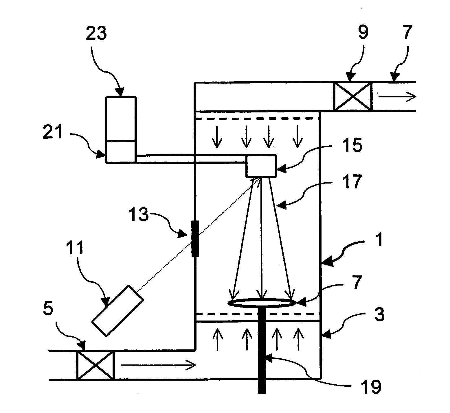
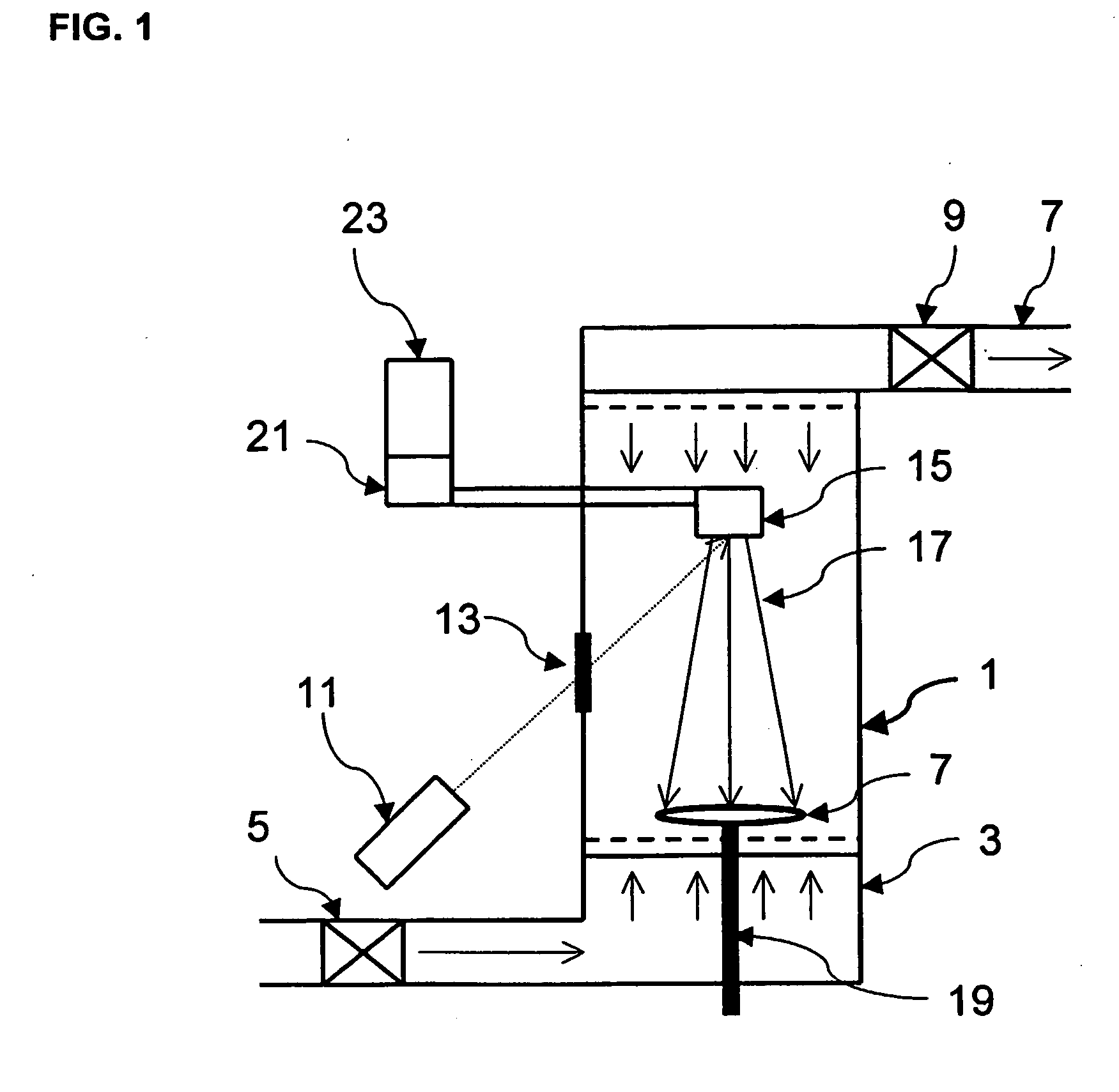
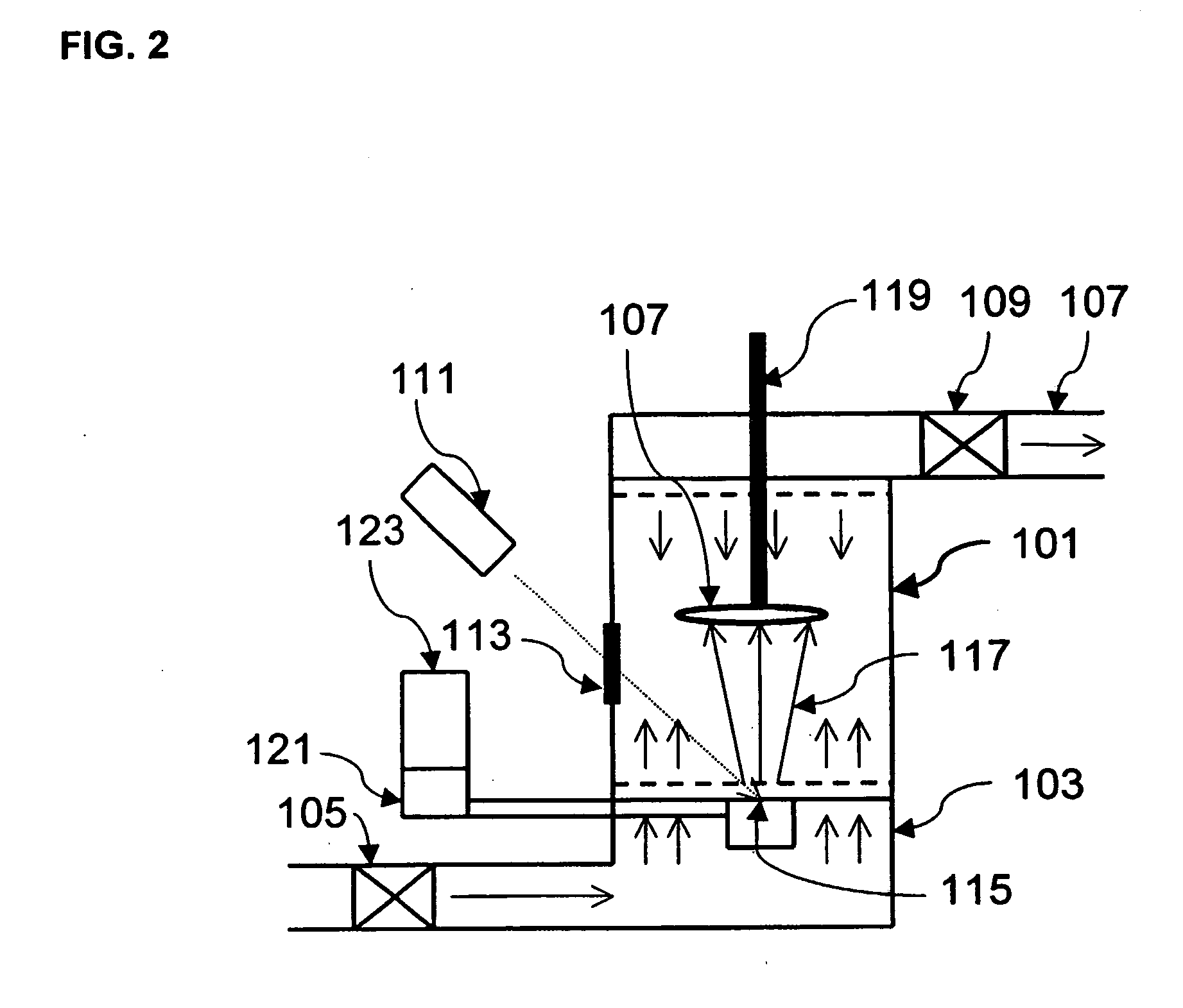
"The present invention provides methods for coating a substrate surface with a target material using a laser to ablate the target material and a gas flow to direct it towards the substrate. The target material can be a biodegradable polymer, biocompatible polymer, chemoselective polymer, polysaccharide, or protein. The coating can be applied to a variety of biomedical devices such as electronic gas sensors, acoustic gas sensors, microfluidic biosensors, microarrays, and stents. The coating can be continuous or discontinuous and can be very thin, with a thickness of less than 1 mm. The invention also includes a coating apparatus and coated substrates."

Problems solved by technology

2002), and chemical modification techniques have been researched to produce biocompatible coatings onto medical devices such as stents, catheters, vascular grafts, contact lenses, ocular implants, oral implants, hip implants, pacemakers / defibrillators, and bonefixation devices, but these processes are limited by poor control of adhesion and composition, rigorous processing conditions, and long reaction times. Pulsed laser deposition (PLD) of ceramics at low pressure (400 mT) have also been described for implant applications (Cotell, Chrisey et al.
A limitation of most surface modification systems, in general, is that multi-stage scale-up from the laboratory to commercial-scale production can be lengthy and difficult, often requiring specialized equipment and expensive solvents.
Additionally, known systems typically produce surface coatings with poor control of the morphology and adhesion that compose undesirable properties.

Method used


Image

  • Method of pulsed laser assisted surface modification
  • Method of pulsed laser assisted surface modification
  • Method of pulsed laser assisted surface modification

Examples


example 1

Biodegradable PLGA Coatings

[0062] A coating of poly(lactic-co-glycolic acid) (PLGA) onto glass slides was produced in accordance with the present invention. PLGA is a resorbable polymer widely used in sutures and injectable drug delivery. A PLGA target was prepared by heating 4.0 grams of PLGA pellets (Lactel 50:50 DL, BPI, IV=0.59, Lot#D01 070) to 110° C. 1 inch metal die for 45 minutes and pressed at 5,000 psi in a Carver press for 30 minutes, allowed to cool to room temperature. The circular target was placed onto a target rotator at the bottom of the coating chamber and a glass slide was fixed on an opposing substrate rotator at the top at a distance of 3 cm from the target. Additional coatings were performed placing 80-mesh mask onto the glass slide to demonstrate the ability of coating defined areas. The chamber was purged to 5 Torr and helium or room air introduced into the chamber from below at 80 to 500 milliliters per minute for several runs with a resulting pressure of ...

example 2

Surface Modification with Tetracycline in PLGA Scaffold

[0063] A coating of 12.5% tetracycline, USP in poly(lactic-co-glycolic acid) (PLGA) was produced onto round glass slide coverslips under similar conditions as Example 1. Tetracycline-loaded resorbable membranes (Webber, Lago et al. 1998) and fibers (Norkiewicz, Breault et al. 2001) have been investigated for local delivery to prevent bacterial growth following periodontal surgery. In addition, bioceramic coatings onto catheters has also been proposed as a method of reducing bacterial attachment (Zabetakis, Cotell et al. 1995). In this example, a PLGA target was prepared by heating 3.5 grams of PLGA (Lactel 50:50 DL, BPI, IV=0.59, Lot#D01070) to 1000° C. in a glass beaker on a hotplate and adding 0.5 gram of tetracycline powder, USP (Spectrum Laboratories, Lot#QW039), mixing with a glass stir bar. The mixture was poured into a 1 inch metal die and allowed to cool to room temperature. The circular target was placed onto a target...

example 3

Biodegradable PLA Coatings

[0065] A coating of poly(1-lactic acid) (PLA) was produced onto a glass slide under similar conditions as Example 1. The target was prepared by heating 4.0 grams of PLA (Medisorb, PLA Methyl Ester 100L, Lot#00-141-5) to 140° C. in a 1 inch metal die for 45 minutes and pressed at 5,000 psi in a Carver press for 30 minutes, allowed to cool to room temperature. The circular target was placed onto a target rotator at the bottom of the coating chamber and a glass slide was fixed on an opposing substrate rotator at the top at a distance of 3 cm from the target. The chamber was purged to 5 Torr and helium or room air introduced into the chamber from below at 80 to 500 milliliters per minute for several runs with a resulting pressure of 5 to 500 Torr, as well as atmospheric pressure. The coating run was performed at laser energies of 150 to 600 mJ / cm2 at a pulse rate of 5 to 40 hertz for 1 to 5 minutes. At the end of the run room air was introduced and the substr...


PUM

PropertyMeasurementUnit
pressureaaaaaaaaaa
pressureaaaaaaaaaa
thicknessaaaaaaaaaa

Abstract

A method comprising providing a target material (115), providing a substrate (107), ablating the target material (115) to form ablated target particulate material (117), directing the ablated particulate material (117) toward the substrate (107) with a gas flow, and coating the substrate surface (107).

Description

[0001] The present application claims priority under 35 U.S.C. § 119 to U.S. Provisional Patent Application No. 60 / 349,557, filed Jan. 22, 2002.BACKGROUND OF THE INVENTION [0002] 1. Field of the Invention [0003] The invention relates to processes for changing the surface properties and / or applying a thin coating to surfaces of a substrate, such as biomedical devices or sensing surfaces that improve surface interactions in gaseous, liquid, or biological environments and devices produced thereby. The substrate may include, but is not limited to, an optical, electronic, or acoustic gas sensor, a microfluidic biosensor or microarray, and a partially or wholly implanted device or any external device in contact with biological fluids and / or surfaces. More particularly, the invention provides new methods for preparing compositions that are coated with ultrafine layers of coating material, such as organic polymeric coating materials, applied through a non-aqueous, non-solvent technique near...

Claims


Application Information

Patent Timeline
Patent Type & Authority Applications(United States)
IPC IPC(8): B05D3/00C23C14/30C23C16/00A61L27/28B05D1/00B05D7/14B05D7/24C23C14/12C23C14/28
CPCA61L27/28A61L2400/18B05D1/00C23C14/28C23C14/06C23C14/12C23C14/228B05D1/60
Inventor TALTON, JAMES D.
Owner NANOTHERAPEUTICS INC
Learn More