Low- Voltage discharge lamp and its manufacturing method

a discharge lamp and low-voltage technology, applied in the manufacture of electric discharge tubes/lamps, cold cathode manufacture, electrode systems, etc., can solve the problems of increasing the power consumption of the lamp, difficulty in mass production of discharge lamps, and partially carbonization, and achieves high efficiency and cost reduction

Inactive Publication Date: 2006-03-16
HARISON TOSHIBA LIGHTING CORP
View PDF6 Cites 12 Cited by
  • Summary
  • Abstract
  • Description
  • Claims
  • Application Information

AI Technical Summary

Benefits of technology

[0012] In the low-pressure discharge lamp according to the present invention, the conductor layer of the external electrode having an even layer with a uniform thickness is formed by dipping the end portion of the tubular glass lamp vessel into the ultrasonic solder bath. Moreover, the conductor layer is hardly separated from the tubular glass lamp vessel and a highly efficient low-pressure dis

Problems solved by technology

However, since the diameter of the tubular glass lamp vessel is very small such as about 3 mm, a complicated machine is required to apply the metallic tape on the tubular glass lamp vessel with high dimensional accuracy and it is difficult to manufacture the discharge lamps in mass production.
Further, in an electrode using such a metallic tape, a power loss is caused in the conductive adhesive made of acrylic resin when a current flows throug

Method used


Image

  • Low- Voltage discharge lamp and its manufacturing method
  • Low- Voltage discharge lamp and its manufacturing method
  • Low- Voltage discharge lamp and its manufacturing method

Examples


first embodiment

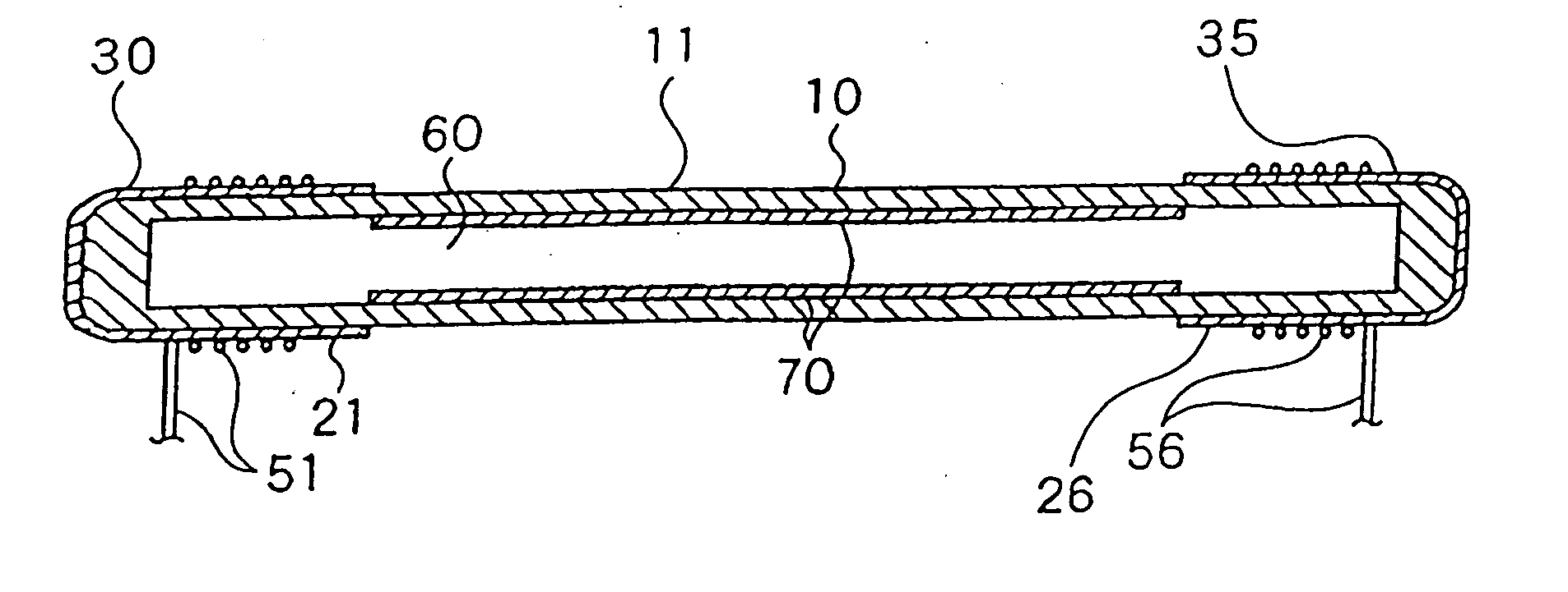
[0019] The embodiments according to the present invention will be now explained with reference to the accompanying drawings. FIG. 1 shows the structure of a dielectric barrier discharge type low-pressure discharge lamp 11 according to the present invention. In the low-pressure discharge lamp 11, a tubular glass lamp vessel 10 is formed with borosilicate glass, having an outer diameter of 2.6 mm, an inner diameter of 2.0 mm, and a total length of 350 mm. The tubular glass lamp vessel 10 is charged with mixed gases of neon and argon at a charge pressure of 60 Torr (composition ratio of neon / argon is 90 mol % / 10 mol %). Further, the tubular glass lamp vessel is also charged with 3 mg of mercury.

[0020] On outer surfaces of both ends of the tubular glass lamp vessel 10, solder dipping layers 30 and 35 are formed respectively as conductor layers of external electrodes 21 and 26. On an inner peripheral wall of the tubular glass lamp vessel 10 excluding the parts where the external electrod...
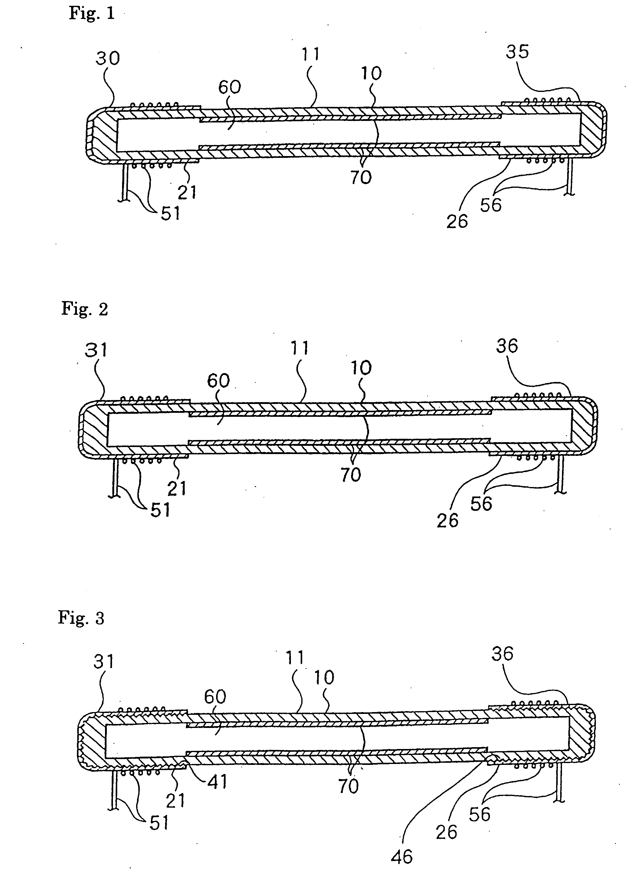
second embodiment

[0036] In the low-pressure discharge lamp 12 having such a construction, the ultrasonic solder dipping method is adopted, thus mass production of a highly efficient low-pressure discharge lamp can be realized at a low price as in the low-pressure discharge lamp 11 according to the Furthermore, according to the embodiment, silver consumption due to adsorption of mercury into the phosphor layer 70 in the glass lamp vessel 10 can be suppressed and silver consumption due to entry of silver into the glass can be prevented. Thus a life span of the lamp can be lengthened.
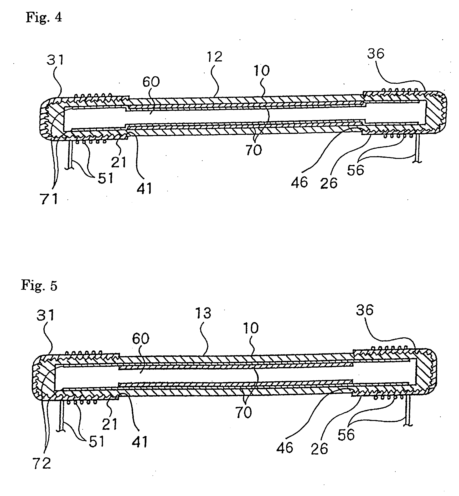
third embodiment

[0037] Next, in a low-pressure discharge lamp 13 shown in FIG. 5, the blasted surfaces 41 and 46 are formed on the outer surfaces of both ends of the tubular glass lamp vessel 10, and the ultrasonic solder dipping layers 31 and 36 are formed as external electrodes 21 and 26 on the surfaces thereof, as in the Further, a metal oxide layer 72 such as aluminum oxide, yttrium oxide, or zinc oxide is formed between the inner surface of the tubular glass lamp vessel 10 and the phosphor layer 70 and on the glass surfaces inside the external electrodes 21 and 26.

[0038] In the low-pressure discharge lamp 13 having such a construction, the ultrasonic solder dipping method is adopted, thus mass production of a highly efficient low-pressure discharge lamp can be realized at a low price similarly to the low-pressure discharge lamp 11 of the second embodiment. Furthermore, according to the embodiment, silver consumption due to entry of silver into the glass surface of the tubular glass lamp vesse...


PUM


Abstract

A low-pressure discharge lamp having a tubular glass lamp vessel 10, on an outer surface of which conductor layers are formed as electrodes 21 and 26. The ultrasonic solder dipping layers 31 and 36 are formed at both ends of the vessel 10 as conductor layers. The end surfaces of the glass lamp vessel are blasted and ultrasonic solder dipping layers are formed on the blasted surfaces 41 and 46 by ultrasonic solder dipping. Conductor layers forme external electrodes 21 and 26, which are in contact with the glass surface more strongly. A low-pressure discharge lamp having the conductor layers of a uniform thickness can be mass-produced at low cost.

Description

FIELD OF THE INVENTION [0001] The present invention relates to a low-pressure discharge lamp and a method for manufacturing it. BACKGROUND OF THE INVENTION [0002] A dielectric barrier discharge type low-pressure discharge lamp having an electrode on the outer surface of a tubular glass lamp vessel (EEFL) is known as an example which is described in the laid-open Japanese-utility model application Shou 61-126559, for example. This low-pressure discharge lamp is charged with ionizable filler such as rare gas or mixed gas of mercury and rare gas inside a tubular glass lamp vessel with both ends sealed. On the inner wall surface of the tubular glass lamp vessel, a phosphor layer is formed as necessary. On the outer surfaces of both ends of the tubular glass lamp vessel, external electrodes are arranged. [0003] The external electrodes are composed of, for example, a metallic tape made of aluminum foil and a conductive adhesive for forming an electrically conductive layer and coiled lead ...

Claims


Application Information

Patent Timeline
IPC IPC(8): H01J65/00H01J9/02H01J9/14H01J9/20H01J9/24H01J61/067H01J65/04
CPCH01J9/02H01J9/14H01J65/046H01J61/0672H01J61/0675H01J9/20H01J2893/0002
Inventor TAKEDA, YUJITAKAYOSHI, KURITAMASAMI, TAKAGI
Owner HARISON TOSHIBA LIGHTING CORP
Why Eureka
Try Eureka