

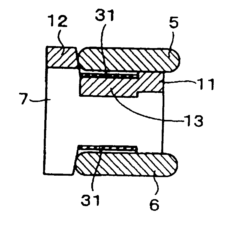
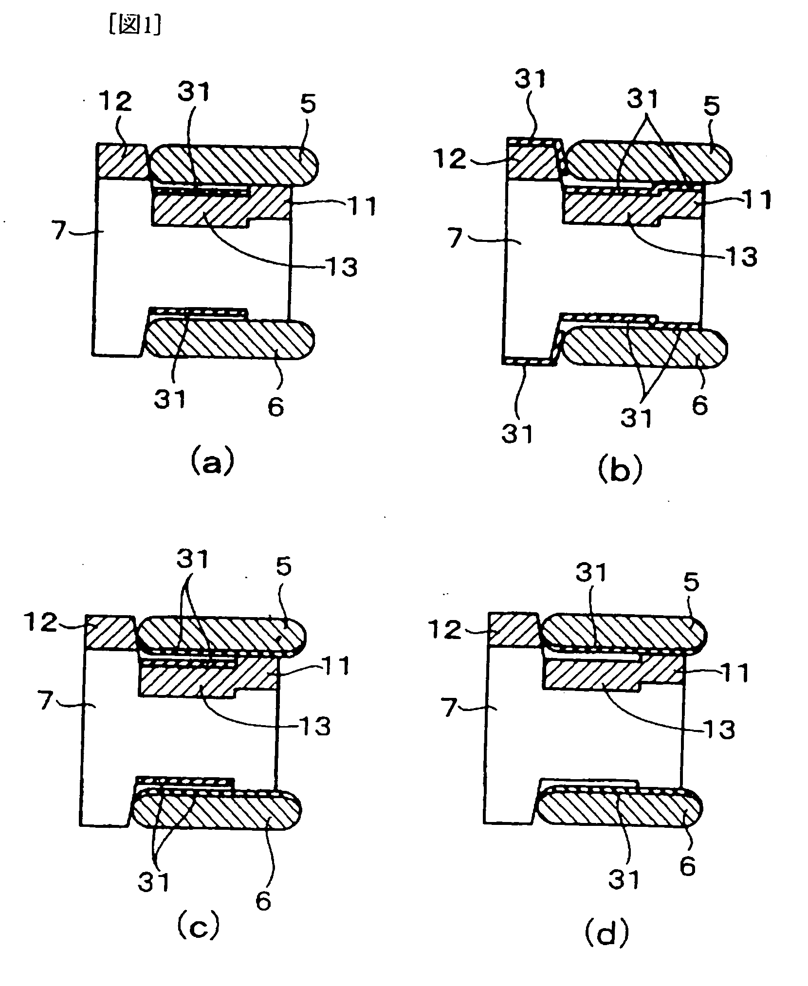
Three piece-combined oil ring
a combined oil control and three-piece technology, applied in the direction of heat treatment equipment, superimposed coating process, furnaces, etc., can solve the problems of increasing oil consumption, reducing tension, and particularly serious corrosion wear, and achieving the effect of reducing tension, poor corrosion resistance, and reducing wear
- Summary
- Abstract
- Description
- Claims
- Application Information
AI Technical Summary
Benefits of technology
Problems solved by technology
Method used
Image

Examples
examples 1-2 (
J1-J2) AND COMPARATIVE EXAMPLE 1 (H1)
[0062] A rolled strip (SUS 304 material) having 2.70 mm of width, 0.25 mm of thickness and 20 mm of length for use as a spacer expander was cut into samples. These samples were degreased, rinsed and subsequently gas-nitrided at 570° C. and 530° C. for 30 minutes in the atmosphere of NH3 90% and N2 10%. For the nitriding, a muffle structure furnace was used. Once the furnace interior was evacuated and then the temperature was increased. Prior to nitriding, the reduction of passivation film was carried out by means of adding a predetermined amount of ammonium chloride at predetermined timing.
[0063] For comparison purposes, the same samples were degreased, rinsed and then salt bath-nitrided at 570° C. for 30 minutes.
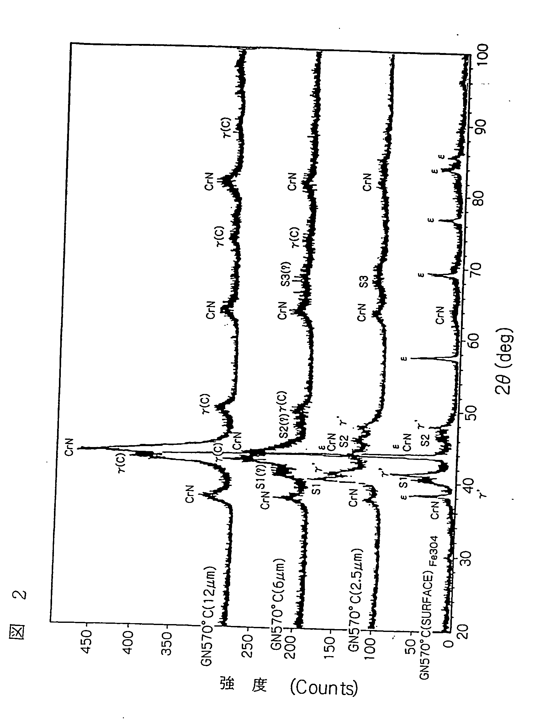
[0064] After the nitriding, for confirming the crystal structural change in the depth direction of the nitriding surface layer, the samples were subjected to electropolishing in the electrolyte consisting of phosphoric acid, oxalic aci...
examples 3-18 (
J3-J18) AND COMPARATIVE EXAMPLES 2-3 (H2-H3)
[0067] A rolled strip (SUS 304 material) having 2.70 mm of width, 0.25 mm of thickness and 20 mm of length was cut into samples as in Example 1. These samples were degreased, rinsed and gas-nitrided in the same atmosphere as Example 1 and under the conditions of temperature and holding time shown in Table 2. Reduction of the passivation film was also carried out as in Example 1. The nitrided samples were subjected to the optical microscope observation of a cross-section of the samples to obtain thickness of the nitriding surface layer and the area ratio (using image analyzer) of the (Fe, Cr, Ni, . . .)4N phase. The samples were etched by a Marble liquid so as to make the decomposed (Fe, Cr, Ni, . . .)4N phase, i.e., to make CrN phase and γ′ phase visibly black. The so-etched samples were photographed. In addition, the Vickers hardness of the outermost surface of the nitriding surface layer under the load of 25 g was measured. The results a...
examples 19-24 (
J19-24) AND COMPARATIVE EXAMPLES 4-5 (H4-H5)
[0069] In order to evaluate in short time the wear in engines, three-piece type combined oil-control rings were manufactured as follows.
[0070] A SUS 304 strip having 2.50 mm of width and 0.25 mm of thickness was shaped into a spacer expander having corrugated form in the axial direction by means of the gear shaping method. The spirally shaped spacer expander blanks were degreased, rinsed and nitrided.
[0071] The nitriding condition was as follows: Example 19—the same as in Example 4; Example 20—the same as in Example 5; Example 21—the same as in Example 7; Example 22—the same as in Example 10; Example 23—the same as in Example 13;: Example 24—the same as in Example 16; Comparative Example 4—the same as in Comparative Example 2; and, Comparative Example 5—the same as in Comparative Example 1.
[0072] After the nitriding, the steps of cutting into specified length, finishing end surfaces were carried out, thereby producing the spacer expande...
PUM
| Property | Measurement | Unit |
|---|---|---|
| temperature | aaaaa | aaaaa |
| temperature | aaaaa | aaaaa |
| thickness | aaaaa | aaaaa |
Abstract
Description
Claims
Application Information