Method for repairing a gas turbine engine airfoil part using a kinetic metallization process

Inactive Publication Date: 2006-11-23
RECAST AIRFOIL GROUP
View PDF2 Cites 25 Cited by
  • Summary
  • Abstract
  • Description
  • Claims
  • Application Information

AI Technical Summary

Benefits of technology

[0084] Depending on the coating process, and the necessity for doing so, the predetermined contact area can be masked off before the step of selectively coating. A sintering heat treatment can be perfomed before the step of performing the hot isostatic heat treatment to limit the occurrence of bubbles on the surface of the hardface coating material aft

Problems solved by technology

During the lifetime of a gas turbine engine, the cold section components of the engine become worn and in need of repair.
The form of distress is often local pitting corrosion and foreign object damage.
Conventional methods for repairing the cold section components of a gas turbine engine are limited to minor blending.
These deforming stresses cause creep rupture and fatigue problems that can result in the failure of the part.
However, like the rotating parts, these parts are subjected to other deformation such as from hot gas erosion and/or foreign particle strikes.
This deformation results in the alteration of the dimensions of the airfoil section.
The alteration of the dimensions of the airfoil section can detrimentally modify the airflow through the gas turbine engine which is critical to the engine's performance.
The repair operations that remove metal by chemical stripping, grit blasting, blending and polishing shorten the life cycle of the vane.
When certain minimum airfoil dimensions cannot be met the part is deemed non-repairable and must be retired from service.
During use, the coating at the cutting surface of the cutting tool is subjected to shearing forces resulting in flaking off the coating of the tool substrate.
The failure is likely to occur at the narrow bonding interface.
Since the coating adheres to the tool bit substrate mostly via a mechanical bond located at a boundary interface, flaking and chipping off the coating of the substrate is likely to occur during use, limiting the service life of the 
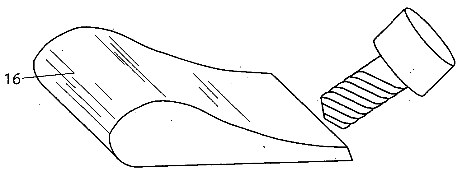
tool bit. FIG. 12(b) is a side view of a prior art tool bit having a fixed wear resistant cutting tip.
During extended use the tool bit is likely to fail at the relatively brittle brazed interface between the metal cutting tip and the tool substrate, and again, the useful service life of the tool bit is limited.
The high speed collision of the metal particles results in very large strain (approximately 80% in the direction normal to impact).
A cast metal component will typically have a number of imperfections caused by voids and contaminants in the cast surface structure.
The manufacture of metal components often entails costly operations to produce products with the desired surface texture, material properties and dimensional tolerances.
However, traditional HIP tr

Method used


Image

  • Method for repairing a gas turbine engine airfoil part using a kinetic metallization process
  • Method for repairing a gas turbine engine airfoil part using a kinetic metallization process
  • Method for repairing a gas turbine engine airfoil part using a kinetic metallization process

Examples


Embodiment Construction

[0154] For purposes of promoting an understanding of the principles of the invention, reference will now be made to the embodiments illustrated in the drawings and specific language will be used to describe the same. It will nevertheless be understood that no limitation of the scope of the invention is thereby intended, there being contemplated such alterations and modifications of the illustrated device, and such further applications of the principles of the invention as disclosed herein, as would normally occur to one skilled in the art to which the invention pertains.

[0155] Referring to FIG. 1(a), in accordance with the present invention, the dimensional differences between pre-repaired dimensions of a turbine engine airfoil part and desired post-repair dimensions of the turbine engine airfoil part are determined (Step One-B). The turbine engine airfoil part has a substrate comprised of a superalloy. A build-up thickness of coating material required to obtain the desired post-re...


PUM

PropertyMeasurementUnit
Fractionaaaaaaaaaa
Fractionaaaaaaaaaa
Fractionaaaaaaaaaa

Abstract

A method of repairing a turbine engine airfoil part includes the step of first determining dimensional differences between pre-repaired dimensions of a turbine engine airfoil part and desired post-repair dimensions of the turbine engine airfoil part. The turbine engine airfoil part has a metal alloy substrate. A build-up thickness is determined of coating material that is required to obtain the desired post-repair dimensions of the airfoil part. A high-density coating process is performed to coat the turbine engine airfoil part substrate with a coating material to build-up a thickness of coating material effective to obtain desired finished dimensions after performing a hot isostatic pressing treatment. The high density coating process comprises the steps of accelerating metal particles in an inert carrier gas, and directing the accelerated metal particles onto the turbine engine airfoil part so that high-speed collision of the metal particles causes deformation of the particles resulting in a large increase in the surface area of the particles producing the controlled buildup of a high density coating of the deformed metal particles. The hot isostatic pressing treatment is performed to obtain a post-repair turbine engine airfoil part having the desired post-repair dimensions and having diffusion bonding between the coating material and the turbine engine airfoil substrate.

Description

BACKGROUND OF THE INVENTION [0001] The present invention pertains to methods for repairing a turbine engine airfoil part. More particularly, the present invention pertains to a method for repairing a gas turbine engine airfoil part using a kinetic metallization process and hot isostatic pressing treatment to form a repaired airfoil part with a selectively built-up coating that is relatively oxide free and affixed to the airfoil part substrate through a tenacious diffusion layer bond. [0002] The present invention can also be used to repair cold section components, and other non-airfoil components on gas turbine engines and other system. [0003] The cold section component of a gas turbine engine includes elements such as a containment ring. The containment ring is typically made of a material such as ams4117 aluminum alloy and is known as 6061 t-6 with the following chemistry 1.0 mg, 0.60 si, 0.28 cu, 0.20 cr. The containment ring is provided annularly around the fan blade assembly. In...

Claims


Application Information

Patent Timeline
IPC IPC(8): B23P6/00
CPCB23K10/027B23K2201/001B23P6/007C23C24/04F01D5/005Y02T50/672Y10T29/49734F05D2300/611F05D2230/40C23C24/087Y10T29/49718Y10T29/49318F05D2230/90B23K2101/001Y02T50/60
Inventor ARNOLD, JAMES E.BLAKE, WAYNE C.
Owner RECAST AIRFOIL GROUP
Why Eureka
Try Eureka