Internal combustion engine/water source system

a technology of internal combustion engine and water source system, which is applied in the direction of machines/engines, mechanical equipment, non-fuel substance addition to fuel, etc., can solve the problems of loss of overall lubricant effectiveness, increase in mechanical wear, and excessive mechanical wear, so as to achieve the effect of reliable liquid water generation, improved operation, and large volume production of automotive vehicles

Inactive Publication Date: 2007-01-11
VETROVEC JAN
View PDF24 Cites 29 Cited by
  • Summary
  • Abstract
  • Description
  • Claims
  • Application Information

AI Technical Summary

Benefits of technology

[0024] Accordingly, it is an object of the present invention to provide a ICE/water source system which can reliably generate liquid water onboard an automotive vehicle. The ICE/water source system of the present invention is simple, lightweight, and inexpensive to manufacture and, therefore, suitable for large volume production of automotive vehicles.
[0025] It is another object of object of the present invention to provide a ICE/water source system that is operational at all atmospheric conditions, that is robust to freezing conditions, and can operate automatically without human intervention.
[0026] It is another object of object of the present invention to provide a ICE/water source system that can supply liquid

Problems solved by technology

First, atomized or vaporous fuel in the air/fuel mixture introduced into the engine cylinders tends to condense onto the cold engine components, such as cylinder walls and the air intake rail.
Condensed hydrocarbon fuels on engine cylinder walls may act as solvents that wash away desirable lubricant films resulting in excessive mechanical wear from reciprocating piston rings in sliding contact with the engine cylinder walls.
The condensed mixture of fuel and lubricant is capable of passing the piston rings, entering the crankcase and contaminating the engine's lubrication reservoir resulting in a loss of overall lubricant effectiveness and a further increase in mechanical wear, even during normal operation.
Second, the condensation of atomized or vaporous fuels onto cold engine cylinder walls results in poor engine performance and delayed engine availability during and immediately after cold engine start-up.
ICE availability is diminished during cold engine start-up due to poor lubricant properties at low temperatures, non-uniform fuel distribution and improper air/fuel mixtures.
Third, if the vehicle is equipped with a catalytic converter increased levels of unwanted pollutants are emitted from the tailpipe for a period of about one to three minutes after cold engine start-up because that is the amount of time normally needed for the ICE exhaust gases to heat the catalytic converter in the exhaust system to an efficient operating temperature.
The undesirable levels of pollutants released during and immediately after cold ICE start-up present a problem of increasing importance.
However, until the catalyst light-off temperature is reached, the ICE exhaust gasses pass through the catalytic converter relatively unchanged, and unacceptably high levels of pollutants such as carbon monoxide, hydrocarbons and nitrogen oxides are released into the atmosphere.
According to some estimates, over 80% of the unacceptable emissions or pollutants are generated by ICE equipped with catalytic converter occur during cold start operations.
However, providing hydrogen gas as a separate fuel at automotive service stations is impractical because hydrogen distribution infrastructure for automotive use is non-existent.
In addition, transport and storage of large quantities of hydrogen represent a very significant safety hazard.
The first method wherein ICE exhaust gases are cooled to below a dew point by rejecting heat to ambient air is rather ineffective on hot days

Method used


Image

  • Internal combustion engine/water source system
  • Internal combustion engine/water source system
  • Internal combustion engine/water source system

Examples


example 1

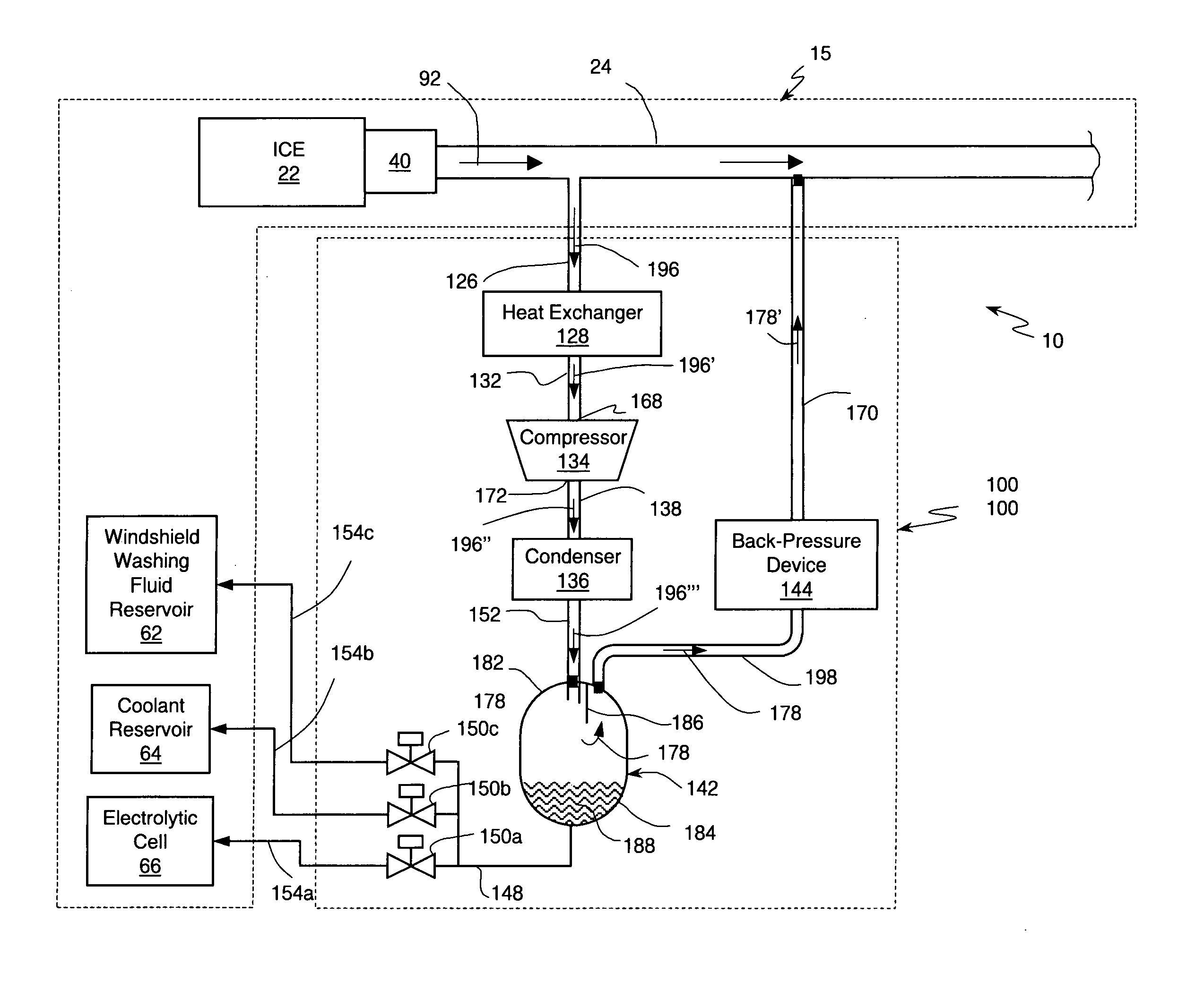
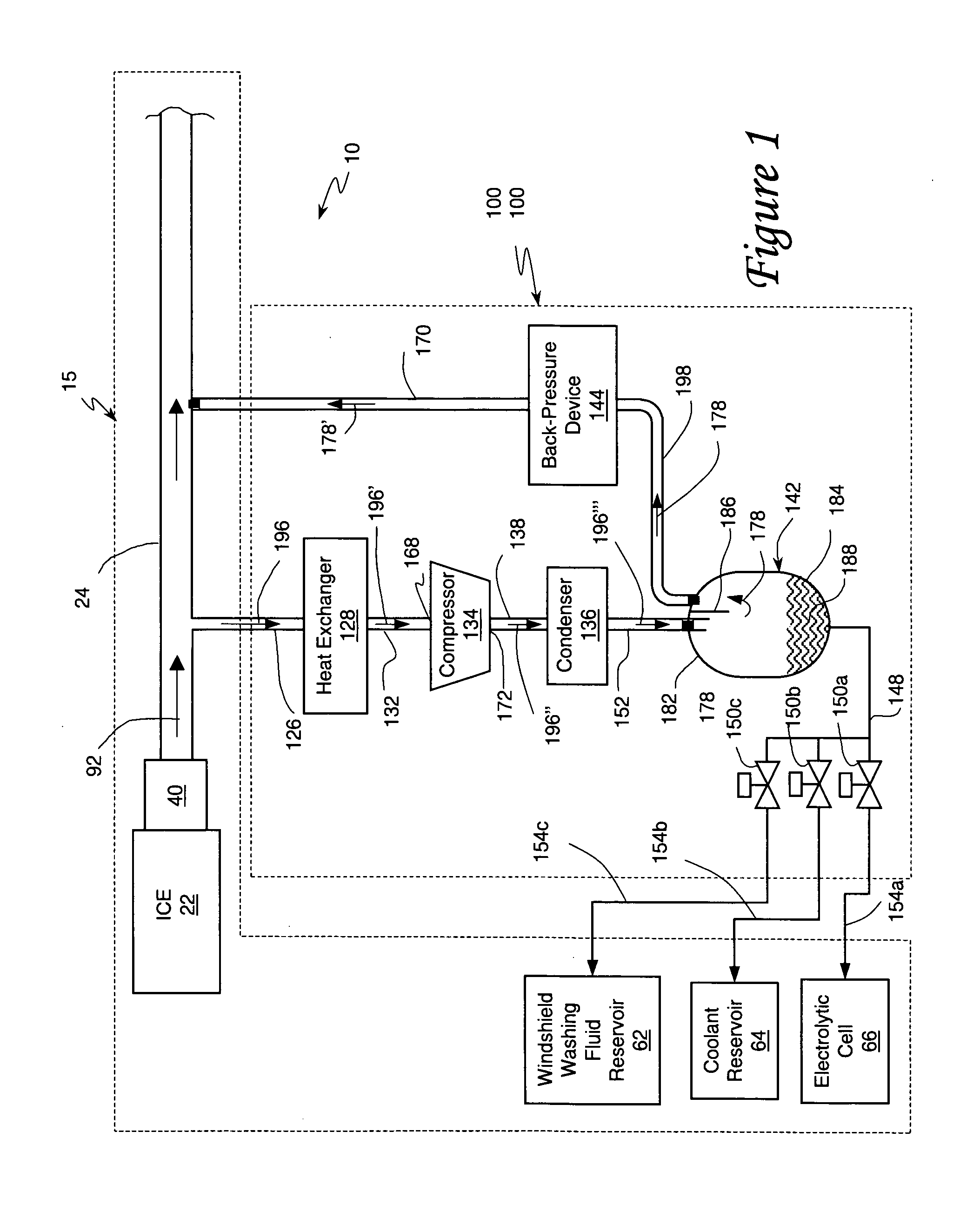
[0044] ICE / water source system 10 operated at a sea level with ambient atmospheric pressure of 760 Torr and at an ambient temperature of 40 degrees Centigrade (104 degrees Fahrenheit). To limit ICE pumping loss ICE designers normally strive to keep the pressure drop in the exhaust duct 24 is very small. This means that the pressure inside the exhaust duct 24 is only slightly higher than the ambient atmospheric pressure. Therefore, the partial pressure of the water vapor in the ICE exhaust gases 92 is about 118 Torr and the dew point is 55 degrees Centigrade. Process stream 196 is drawn from exhaust gas stream 92 and cooled in heat exchanger 128 to a temperature of 60 degrees Centigrade. Because this temperature is above the dew point of the exhaust gas stream 92, no condensation is expected to occur before process stream 196′ reaches the compressor 134. One liter of the gases in process stream 196′ contains approximately 0.1 grams of water vapor. Compressor 134 is operated to draw t...


PUM


Abstract

An internal combustion engine system for automotive vehicle wherein liquid water is produced by cooling a portion of exhaust gases at elevated pressure to induce condensation. The use of elevated pressure allows condensation to occur at a higher dew point which is easier to realize with cooling by ambient air. Liquid water condensate is collected and provided to an electrolytic cell for electrolysis into gaseous hydrogen and oxygen. Hydrogen gas generated by the cell is used by the internal combustion engine to reduce internal combustion engine wear and to reduce exhaust pollutants especially during start-up. Alternate uses of the liquid water include a replenishment of engine coolant and window washing fluid.

Description

CROSS-REFERENCE TO RELATED APPLICATIONS [0001] Not Applicable FEDERALLY SPONSORED RESEARCH [0002] Not Applicable SEQUENCE LISTING OR PROGRAM [0003] Not Applicable FIELD OF THE INVENTION [0004] The present invention relates to an apparatus and method for providing liquid water on-board an automotive vehicle. More particularly, the present invention relates to supplying water to an electrolytic cell for generation of hydrogen for improving the cold start-up of internal combustion engines. BACKGROUND OF THE INVENTION [0005] The primary motivation for producing water onboard an automotive vehicle is to use such water for electrolytic generation of hydrogen gas which, during a startup, can be fed into the intake of an automotive internal combustion engine (ICE) to reduce engine wear and / or into an engine exhaust system to reduce pollutants. [0006] There are several problems that must be overcome during the start-up of a cold ICE. First, atomized or vaporous fuel in the air / fuel mixture i...

Claims


Application Information

Patent Timeline
IPC IPC(8): F01N5/00F01N5/02F01N3/02
CPCF01N5/02F01N2240/22F02B1/12F02B37/00F02M25/0727Y02T10/16F02M25/074F02M25/12Y02T10/121Y02T10/144F02M25/0739F02M26/23F02M26/34F02M26/35Y02T10/12
Inventor VETROVEC, JAN
Owner VETROVEC JAN
Why Eureka
Try Eureka