Metal oxide dispersion for dye-sensitized solar cells, photoactive electrode and dye-sensitized solar cell

a solar cell and metal oxide technology, applied in the direction of cell components, final product manufacturing, sustainable manufacturing/processing, etc., can solve the problems of poor photoelectric conversion efficiency, heavy weight, and high cost, and achieve the effect of improving photoelectric conversion efficiency and reducing cos

Inactive Publication Date: 2007-03-29
SHOWA DENKO KK
View PDF11 Cites 2 Cited by
  • Summary
  • Abstract
  • Description
  • Claims
  • Application Information

AI Technical Summary

Benefits of technology

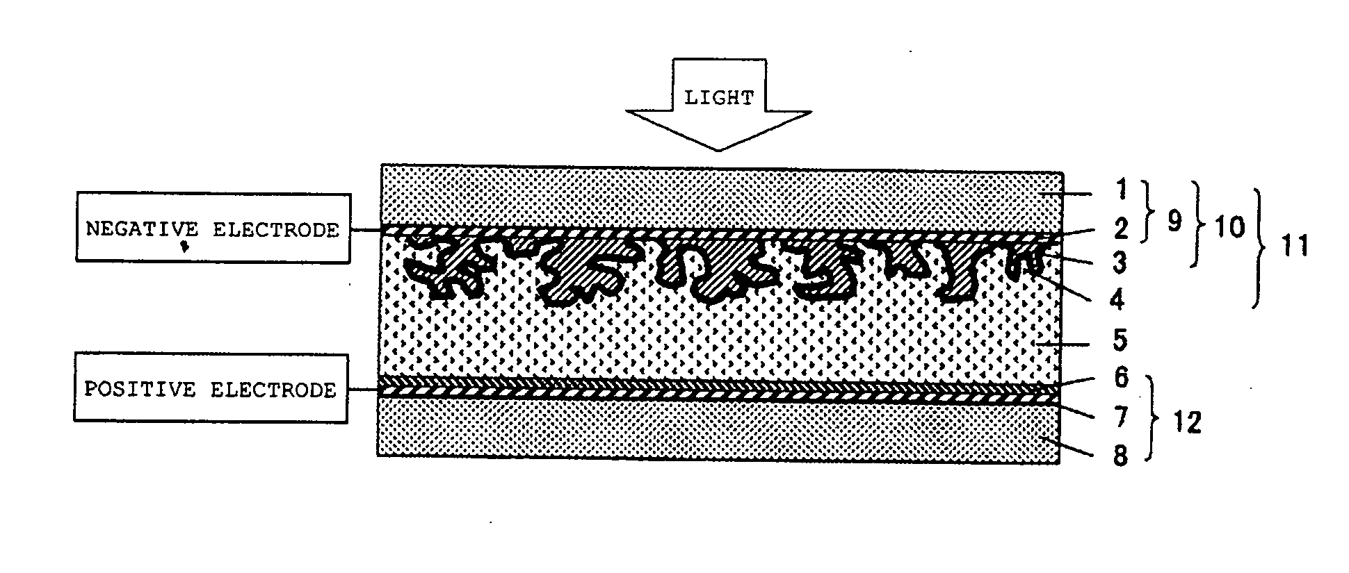
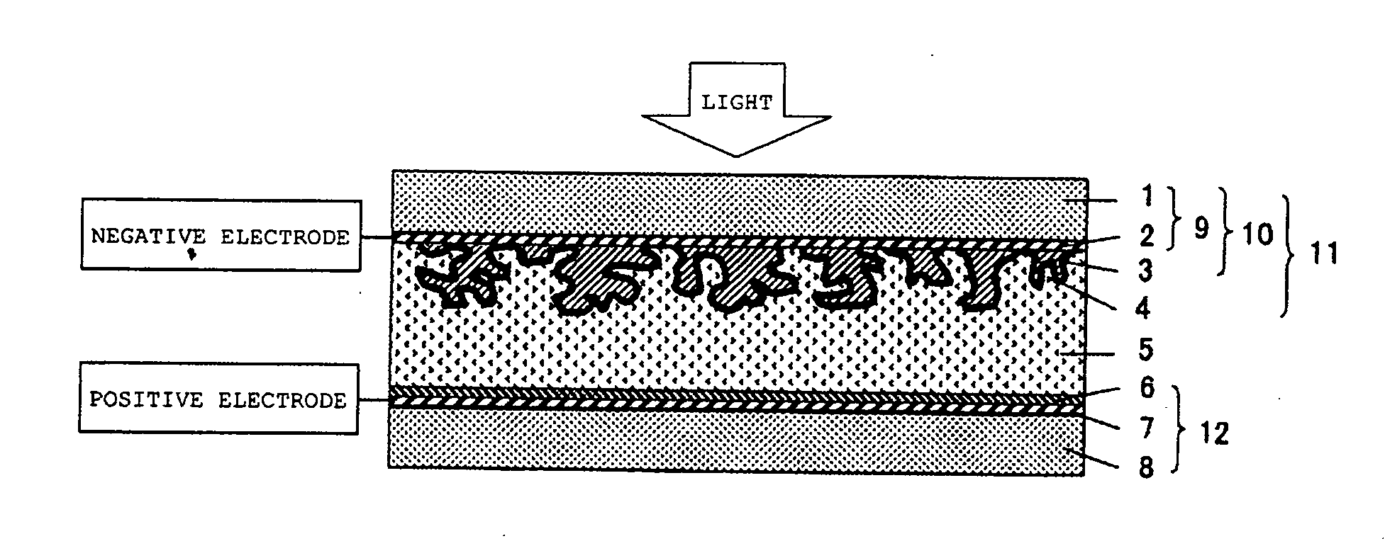
[0013] Therefore, an object of the present invention is to provide a method for producing a photoactive electrode for dye-sensitized solar cells capable of forming a porous metal oxide film on a sheet-shaped electrode without using high temperatures.
[0014] Another object of the present invention is to provide a dye-sensitized solar cell which is light in weight, flexible and inexpensive having a substrate of a sheet-shaped electrode (for example, a resin which is highly transparent, inexpensive, and light in weight and which has freedom in shape) or an electroconducting film (for example, indium tin oxide) which have not been able to maintain the performance thereof in high temperature heat treatment as conducted in the production process of conventional dye-sensitized solar cells.
[0015] As a result of extensive studies with a view to achieving the above-mentioned objects, the inventors of the present invention have found that by coating a metal oxide dispersion composed of metal oxide fine particles, a small amount of a specific polymer binder, and a solvent on a sheet-shaped electrode and then evaporating the solvent, a state where the metal oxide fine particles are bound to each other with the binder can be maintained, that where titanium oxide is used as the metal oxide, one that is produced by a gas phase method is particularly preferable, and that by adopting a spraying method when coating the metal oxide dispersion on the sheet-shaped electrode, porosity of the metal oxide film is increased, thereby achieving the present invention.

Problems solved by technology

From these reasons, production of solar cells by the conventional technique requires a large amount of heat energy and the sheet-shaped electrode used for the photoactive electrode requires heat resistance, so that the practically usable substrate is limited to fluorine-doped tin oxide glass, which has the feature of high heat resistance but is expensive, heavy and poor in shape freedom.
In other words, in accordance with the conventional method, it is difficult to fabricate dye-sensitized solar cells with a substrate of sheet-shaped electrode which is light in weight, inexpensive and flexible, for example, a resin, etc., while maintaining an acceptable photoelectric conversion efficiency or with a sheet-shaped electrode having indium tin oxide as inexpensive electroconducting film.
As a result, they have disadvantages of a great decrease in photoelectric conversion efficiency in that the electrolytic layer absorbs most part of light to cause a great energy loss and that the most part of photoelectrons is generated at sites remotest from the sheet-shaped electrode of metal oxide film, so that photoelectrons are restricted in their movement due to electric resistance of the metal oxide.
Furthermore, the substrate of the sheet-shaped electrode which can endure corrosion by iodine used as an electrolyte of the dye-sensitized solar cell is limited to expensive metals such as titanium, tantalum, and niobium, so that the dye-sensitized solar cells produced by these methods become expensive.
However, since this method fails to make the metal oxide film porous, the fabricated photoactive electrode has a problem in that it has greatly decreased performance as compared with the conventional porous photoactive electrode which is fabricated by the conventional high temperature heat treatment.
Even if a porous metal oxide film were formed by this method, adhesion between the metal oxide fine particles would be insufficient because of absence of sintering treatment at high temperatures and thus the mechanical strength of the metal oxide film would be insufficient.
Therefore, it is expected that slight mechanical vibration which the metal oxide electrode receives, temperature variation which the cell is susceptible to or the like deteriorates contact between the metal oxide fine particles.
That is, the dye electrode fabricated by this method will not be able to maintain the performance for a long time.
Taking titanium oxide as an example, one produced by a method which is called as a wet method generally used for dye-sensitized solar cells, for example, titanium oxide produced through hydrolysis of a metal alkoxide and supplied in the form of a solvent dispersion, is not suitable for the case where sintering is performed at low temperatures.
This is because organic substances used in the production process are adsorbed and remain on the surface of such metal oxide fine particles, which deteriorates contact between the fine particles, so that movement of electrons are not performed smoothly, resulting in decreased performance.

Method used


Image

  • Metal oxide dispersion for dye-sensitized solar cells, photoactive electrode and dye-sensitized solar cell
  • Metal oxide dispersion for dye-sensitized solar cells, photoactive electrode and dye-sensitized solar cell

Examples


example 1

[0106] In a mortar, 100 g of titanium oxide (P25, manufactured by Nippon Aerosil Co., Ltd.; titanium oxide prepared by a gas phase method; D90=3.1 μm; distribution constant n=1.4), 0.5 gof poly (N-vinylacetamide) (VIAC GE-191, manufactured by Showa Denko K. K.), and 400 g of water were dispersed to obtain a metal oxide dispersion. This was coated on a glass electrode (CS-4S230, glass with a fluorine-doped tin oxide film, manufacturedby Nippon Sheet Glass Co., Ltd.) by a doctor blading method (using a 40 μm applicator) and then left to stand in a room for 2 hours to obtain a photoactive electrode having a film thickness of 6 μm. Then, this was immersed in an ethanol solution of ruthenium complex dye (RuL2(NCS) 2 manufactured by Kojima Chemical Reagents, Inc.) for 3 hours to obtain a dye electrode. An excess of metal oxide film on the dye electrode was scraped off with a cutter knife so that the metal oxide film had a size of 5×5 mm. On the other hand, platinum having a thickness of 0...

example 2

[0107] A dye-sensitized solar cell was fabricated in the same manner as in Example 1 except that in the metal oxide dispersion, 0.1 g of N-vinylacetamide / sodium acrylate copolymer (VIAC GE-195, manufactured by Showa Denko K. K.) was used in place of poly(N-vinylacetamide). This solar cell had a photovoltaic force of 3.3 mW / cm2.

example 3

[0108] A dye-sensitized solar cell was fabricated in the same manner as in Example 1 except that in the metal oxide dispersion, 1 g of polytetrafluoroethylene (F-104, manufactured by Daikin Industries, Ltd.) was used in place of poly(N-vinylacetamide) and 400 g of methylcellosolve was used in place of water as a solvent. This solar cell had a photovoltaic force of 2.8 mW / cm2.


PUM

PropertyMeasurementUnit
temperatureaaaaaaaaaa

Abstract

(1) A metal oxide dispersion for a dye-sensitized solar cell, which contains metal oxide fine particles, a binder composed of a polymer compound having an action to bind to the fine particles and a solvent; (2) a method for producing a photoactive electrode for a dye-sensitized solar cell by coating a dispersion containing the above-mentioned binder and metal oxide fine particles on a sheet-shaped electrode; (3) a photoactive electrode for a dye-sensitized solar cell, obtained by the method, which electrode has metal oxide containing the above-mentioned binder and metal oxide fine particles; and (4) a dye-sensitized solar cell with the above-mentioned photoactive electrode. According to the present invention, a porous metal oxide film can be formed without performing sintering at high temperatures, so that a flexible, inexpensive dye-sensitized solar cell can be obtained in which a resin material which has high transparency, is inexpensive and light in weight and has freedom in shape can be used as a sheet-shaped electrode substrate.

Description

CROSS-REFERENCE TO RELATED APPLICATIONS [0001] This application is a Divisional of U.S. application Ser. No. 10 / 468,679, which is a 371 of PCT / JP02 / 01473 filed Feb. 20, 2002; the above-noted application incorporated herein by reference in its entirety.TECHNICAL FIELD [0002] The present invention relates to a metal oxide dispersion for dye-sensitized solar cells, which are photoelectric conversion elements, a photoactive electrode for dye-sensitized solar cells with the metal oxide dispersion and to a production method therefor as well as to a dye-sensitized solar cell with the photoactive electrode. BACKGROUND ART [0003] The prototype of a dye-sensitized solar cell was a photoelectric conversion element or solar cell that Graezel, et al. of Ecole Polytechnique Federale de Lausanne first reported in 1991 (M. Graezel, Nature, 353, 737 (1991)), and generally called a dye-sensitized solar cell, a wet-type solar cell, or a Graezel-type solar cell. The feature of the photoelectric convers...

Claims


Application Information

Patent Timeline
Patent Type & Authority Applications(United States)
IPC IPC(8): H01L23/58H01L31/04H01G9/20H01L31/18H01M4/00H01M14/00
CPCH01G9/2009H01G9/2031Y02E10/542H01M4/00H01M14/005H01G9/2059Y02P70/50H01L31/04H01L31/18H01M14/00
Inventor MUROFUSHI, KATSUMIKONDO, KUNIOSATO, RYUSUKE
Owner SHOWA DENKO KK
Why Eureka
Try Eureka