Synthesis and use of nanocrystalline zeolites

a technology of nanocrystalline zeolites and zeolites, which is applied in the direction of nitrous oxides, physical/chemical process catalysts, silicon compounds, etc., can solve the problems of long synthesis time, adverse environmental effects, low product yield, etc., and achieves the elimination of long nucleation and growth times, high yield, and high yield

Inactive Publication Date: 2007-03-29
UNIV OF IOWA RES FOUND
View PDF21 Cites 36 Cited by
  • Summary
  • Abstract
  • Description
  • Claims
  • Application Information

AI Technical Summary

Benefits of technology

[0008] Embodiments of the present invention demonstrate the synthesis of nanocrystalline zeolites in a higher yield than performed or contemplated before, by periodically removing nanocrystals from the synthesis solution and reusing the synthesis solution. Since the yield of nanocrystalline zeolite product is very low, only a small portion of nutrients in the synthesis are consumed and the clear solution composition is very close to the original synthesis solution composition. In addition, since only zeolite crystals that are heavy enough to be separated from the clear solution are removed, very small zeolite crystals are still present in the clear solution and can serve as nucleation sites, directly growing into larger crystals. Long nucleation and growth times are thus eliminated. Embodiments of the present invention synthesize nanocrystals more efficiently, more quickly, with higher yields and obtain more consistent crystal sizes than previously kno

Problems solved by technology

Such methods synthesize nanocrystalline zeolites at low temperature and ambient pressure which leads to low product yields and long synthesis times. The long synthesis times are a result of the low temperature causing slow nucleation and crystal growth.
The remaining synthesis solution is usually discarded after the nanocrystalline zeolites are recovered resulting in adverse environmental ef

Method used


Image

  • Synthesis and use of nanocrystalline zeolites
  • Synthesis and use of nanocrystalline zeolites
  • Synthesis and use of nanocrystalline zeolites

Examples


example 1

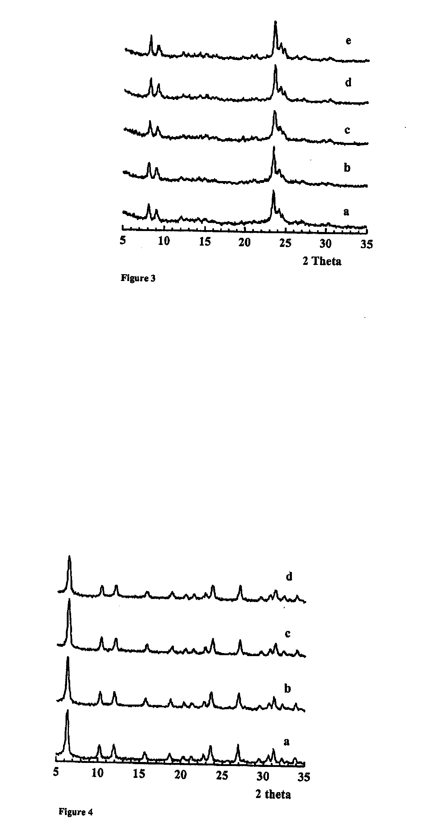
[0059]FIGS. 3 and 4 depict the X-ray diffraction (XRD) powder patterns of silicalite-1 and Y zeolites, respectively, obtained from multiple rounds of zeolite synthesis in which the clear solution recovered after removal of zeolite nanocrystals was reused. The patterns (a)-(e) shown in FIG. 3 correspond to consecutive batches (1-5) of silicalite-1 zeolites. The patterns (a)-(d) shown in FIG. 4 correspond to the first, fourth, seventh and tenth batch of Y zeolites. Each XRD pattern is consistent with the silicalite-1 or Y zeolite structure, respectively. The intensities and line widths of the XRD peaks are similar to each other for each zeolite, suggesting that the different batches of the same zeolite have similar crystal sizes.

[0060] The BET surface areas (of as-synthesized samples) and the Si / Al ratios (for Y zeolites) were measured and are listed in FIG. 5 along with the cumulative nanocrystalline zeolite yields for each batch. The zeolite yield was calculated from the initial sy...

example 2

Zeolite Sample Preparation and Materials

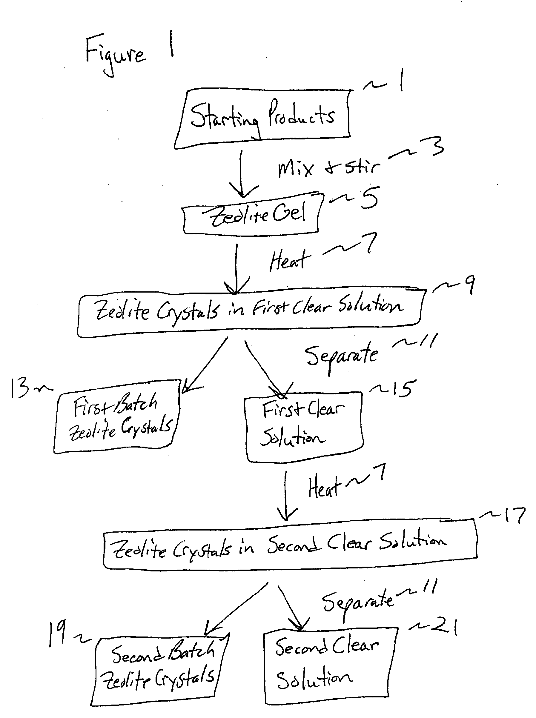
[0068] Nanocrystalline NaY zeolite was synthesized using clear solutions as discussed above. Sodium hydroxide (NaOH), aluminum isopropoxide, tetramethylammonium hydroxide (TMAOH) and distilled water were mixed and stirred until the resulting mixture became a clear solution. Then tetraethyl orthosilicate (TEOS) was added to the clear solution. The clear solution mixture was stirred overnight to ensure complete hydrolysis of the aluminum and silicon sources. The final clear synthesis gel had the following composition: 0.07Na:2.4TMAOH:1.0Al:2.0Si:132H2O:3.0i-PrOH:8.0EtOH (mol ratio), the latter two alcohols came about from the hydrolysis of the aluminum isopropoxide and TEOS, respectively. In order to optimize the formation of small NaY crystals, the sodium content was intentionally set too low relative to aluminum content in the synthesis gel. The clear solution was transferred into a 500 ml flask equipped with an air cooled condenser and was ...

example 3

Solid State MAS NMR Experiments

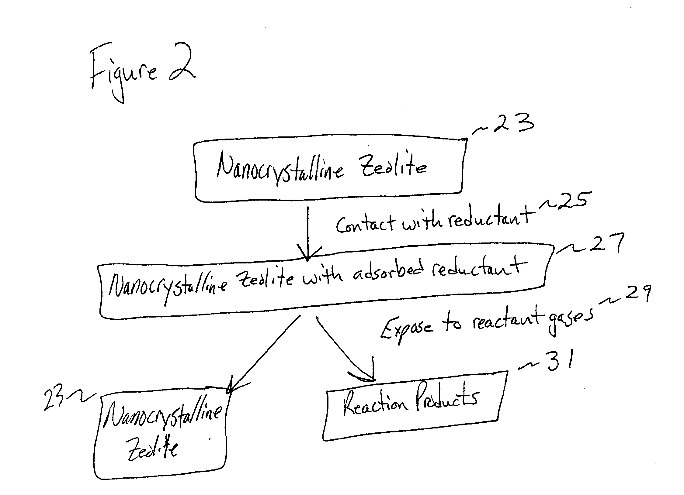
[0073] Approximately 0.2 g of zeolite was impregnated with an aqueous solution of labeled urea (13C and 15N). Samples with adsorbed urea were allowed to dry at room temperature and were placed into pyrex sample tubes that were degassed on a vacuum rack. To prepare samples containing labeled urea and nitric oxide and oxygen, the nitric oxide and oxygen were introduced to the zeolite sample while still attached to the vacuum rack. Then, the pyrex sample tube was sealed while the sample was immersed in liquid nitrogen. The sealed samples were heated for 1 hour at the desired temperatures. Samples were allowed to cool to room temperature for the NMR measurements.

[0074] Magic angle spinning (MAS) NMR spectra were obtained using a 7 Tesla wide bore Bruker cryomagnet and a TecMag Discovery console. The Larmour frequencies for 13C and 15N were 75.470 MHz and 30.425 MHz, respectively. A Chemagnetics double-channel 7.5 mm pencil MAS probe was used to spin rot...


PUM

PropertyMeasurementUnit
Volumeaaaaaaaaaa
Fractionaaaaaaaaaa
Fractionaaaaaaaaaa

Abstract

Embodiments of the present invention relate to a method for synthesizing nanocrystalline zeolites, the method comprising contacting starting products that comprise a solvent, a silicon source, a cation base, an organic template, and an aluminum source, or any combination thereof sufficient to produce a zeolite gel by hydrolysis, heating the zeolite gel sufficient to produce a first batch of zeolite crystals and a first clear solution, separating the first batch of zeolite crystals from the first clear solution, heating the first clear solution sufficient to produce a second batch of zeolite crystals and second clear solution and separating the second batch of zeolite crystals from the second clear solution. In addition, embodiments relate to a method of using nanocrystalline zeolites, the method comprising contacting a nanocrystalline zeolite with a reductant sufficient to produce a nanocrystalline zeolite with adsorbed reductant and exposing the nanocrystalline zeolite with adsorbed reductant to reactant gases sufficient to obtain reaction products and the nanocrystalline zeolite.

Description

RELATED APPLICATION [0001] This application claims the benefit of U.S. Provisional Patent Application Ser. No. 60 / 671,837 filed Apr. 15, 2005, which is incorporated herein by reference.STATEMENT OF GOVERNMENT RIGHTS [0002] This invention was made, at least in part, with a grant from the Government of the United States of America (Grant No. EPA-R82960001 from the Environmental Protection Agency). The Government may have rights in the invention.FIELD OF TECHNOLOGY [0003] Embodiments of the present invention relate to the fields of nanocrystalline zeolite synthesis and applications thereof. Specifically, the embodiments relate to methods of efficiently synthesizing nanocrystalline zeolites and the use of nanocrystalline zeolites as catalysts and reaction sites for selective catalytic reduction of reactant gases. BACKGROUND OF THE INVENTION [0004] Zeolites have well-defined, crystalline structures with pores that are in molecular size range, ion exchangeable sites and high hydrothermal ...

Claims


Application Information

Patent Timeline
IPC IPC(8): C01B39/00C01B39/04C01B33/36C01B21/00C01C1/00C01C1/02
CPCB01D2255/50Y02C20/10B01D2257/404B01J29/035B01J29/084B01J35/0013B82Y30/00C01B21/02C01B21/22C01B37/02C01B39/02C01B39/04C01B39/205C01B39/24C01P2002/72C01P2002/82C01P2002/86B01D2257/402
Inventor LARSEN, SARAHGRASSIAN, VICKISONG, WEIGUOLI, GONGHU
Owner UNIV OF IOWA RES FOUND
Why Eureka
Try Eureka