Short arc type high voltage electrical discharge electrode, short arc type high voltage electrical discharge tube, short arc type high voltage electrical discharge light source apparatus, and their manufacturing methods

a technology of high voltage electrical discharge and manufacturing methods, which is applied in the manufacture of electrode systems, cold cathode manufacturing, and electric discharge tubes/lamps. it can solve the problems of affecting the yield and uniformity of laser light, the uneven irradiation power, and the change of arc spots and arc temperature. , to achieve the effect of improving yield and uniform properties, high reliability and high durability

Inactive Publication Date: 2007-05-17
SONY CORP
View PDF1 Cites 12 Cited by
  • Summary
  • Abstract
  • Description
  • Claims
  • Application Information

AI Technical Summary

Benefits of technology

[0052] Consequently, it is possible to manufacture a short arc type high voltage electrical discharge electrode having improved yield and uniform properties, and high durability and high reliability.
[0053] Consequently, the manufacturing method of the short arc type high voltage electrical discharge tube according to the embodiment and the manufacturing method of the short arc type high voltage electrical discharge light source apparatus according to the embodiment, which electrical discharge tube and which light source apparatus have been formed by applying the manufacturing method of the short arc type high voltage electrical discharge electrode, can manufacture a short arc type high voltage electrical discharge tube which has high reliability, stable characteristics and excellent durability.
[0054] In the short arc type high voltage electrical discharge electrode according to the present embodiment, the contact area between the electrode main body and the electrode center spindle is within a range of from 0.9 mm2 to 3.2 mm2. Thereby, in case the present invention is applied to an electrical discharge tube or a light source apparatus, the thermal conductivity from the tip of the electrode main body to the inner wall of the electrical discharge space of the electrical discharge tube body via the electrode center spindle becomes large, and consequently the temperature of the inner wall of the electrical discharge tube can be efficiently raised. Thereby, the luminous efficiency is more improved. Consequently, further improvement of the luminance reliability can be achieved.
[0055] By applying the short arc type high voltage electrical discharge electrode in which the contact area between the electrode main body and the electrode center spindle is within a range of from 0.9 mm2 to 3.2 mm2 to the short arc type high voltage electrical discharge tube according to the present invention and to the short arc type high voltage light source apparatus according to the present invention, the luminous efficiency is more improved, and further improvement of the luminance reliability can be achieved.

Problems solved by technology

However, this manufacturing method and the structure cannot perform one point irradiation of the laser light because a laser irradiation unit necessary at the time of the melting with the YAG laser has a depth and an extent.
Consequently, the focus of the irradiated laser light is easily shifted at each part, and the irradiation power becomes uneven.
Thereby, the electrode temperature at the time of electrical discharge operation is dispersed, and changes of the arc spot and the unevenness of the arc temperature arise.
However, in the case of such a configuration, because a material containing a binder therein is compressed together with the metal powder constituting the sintered electrode around the rod core pin at the time of sintering, the rod core pin is subjected to high temperature processing in the state in which the rod core pin touches the binder.
Owing to such embrittlement, the existence of distortion, and the like, there is the possibility that the rejection rate becomes high, that the uniformity of characteristics is inferior, and that the problems of the durability and the reliability of a heat cycle of high temperature heating at the time of operation and fall of temperature at the time of non-operating arise.
But, because the sintered body of tungsten is poor in elasticity, the pressing method cannot be applied to the sintered body.
However, a temperature rise of the electrode mainly by ion impact is caused, and it becomes an issue of shortening of life caused by the consumption of the electrode owing to heat and the promotion of the crystallization (the so-called devitrification) of the inner wall of a quartz tube.
But, if the diameter of the electrode center spindle is thickened, the danger of resulting in an explosion increases owing to the generation of distortion of quartz (SiO2) caused by the difference of the coefficients of thermal expansion between the tungsten W (including tungsten as the principal component) and the quartz of the electrode material at the quartz tube sealing portion.

Method used


Image

  • Short arc type high voltage electrical discharge electrode, short arc type high voltage electrical discharge tube, short arc type high voltage electrical discharge light source apparatus, and their manufacturing methods
  • Short arc type high voltage electrical discharge electrode, short arc type high voltage electrical discharge tube, short arc type high voltage electrical discharge light source apparatus, and their manufacturing methods
  • Short arc type high voltage electrical discharge electrode, short arc type high voltage electrical discharge tube, short arc type high voltage electrical discharge light source apparatus, and their manufacturing methods

Examples


example 1

[0100] In this example, the powder molded body was obtained by the metal powder injection molding method.

[0101] In this case, a paste of a kneaded material in the state in which metal powder and a binder were kneaded was obtained.

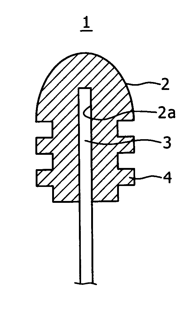
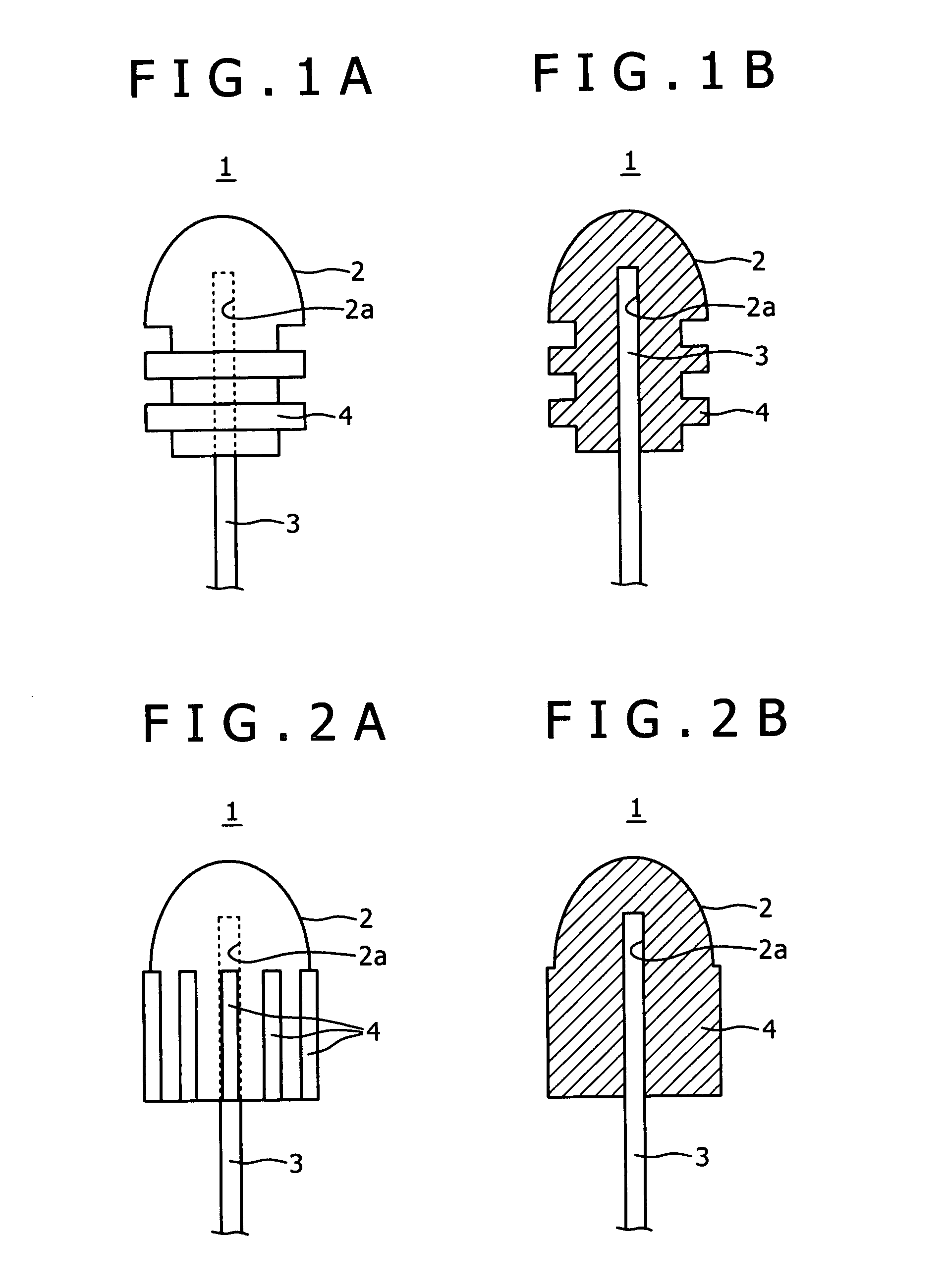
[0102] Tungsten powder or tungsten powder consisting of tungsten (W) as the principal component and the so-called dopant, such as kalium (K), rhenium (Re) and the like, which suppressed recrystallization and suppressed embrittlement, within 5 wt % or less, preferably 100 ppm or less, could be used as the metal powder. The metal powder and a binder of paraffin series or the like were kneaded to acquire the paste mentioned above. The paste was being heated to about 100° C. to about 200° C. as the need arose while the pressure injection molding of the paste into a metal mold having an inner form corresponding to the outer form of the electrode main body 2 of the object was performed. The powder molded body molded in such a way was taken out of the metal mold...

example 2

[0118] In this example 2, the manufacturing method of a powder molded body was performed by the powder pressing.

[0119] In the powder pressing method, granulated powder obtained by the granulation of mixed powder into a granular state which powder was obtained by mixing a binder such as paraffin series into tungsten powder of tungsten or tungsten containing an added dopant similar to those described in the example 1 was filled up into a pressing metal mold, and the granulated powder was subjected to the press molding by, for example, the vertical punching method.

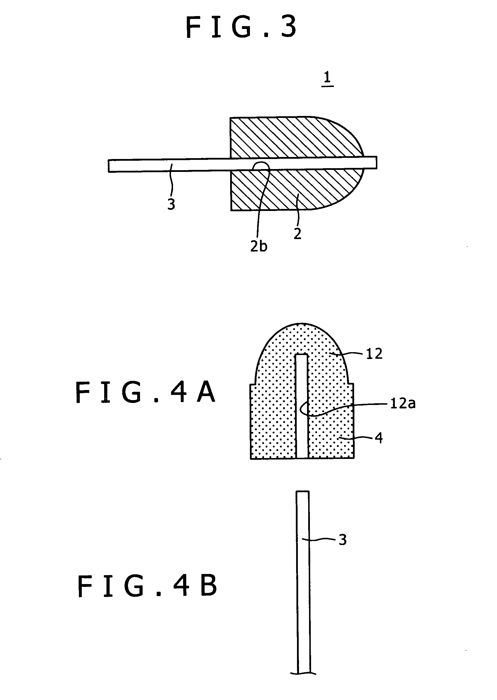
[0120] Thus, the powder molded body of the electrode main body was produced. To this powder molded body, the same temporary sintering, i.e. the first sintering, as that of the example 1 was performed, and the temporarily sintered electrode main body 12 was manufactured.

[0121] On the other hand, similarly in the example 1, the electrode center spindle 3 was prepared, and the electrode center spindle 3 was inserted into the ...

example 3

[0123] In the present example, the short arc type high voltage electrical discharge electrode 1 was produced by setting the contact area of the electrode center spindle 3 and the electrode main body 2 to 0.9 mm2 to 3.2 mm2 in the manufacturing methods of the examples 1 and 2. In the example 3, the excellent short arc type high voltage electrical discharge electrode 1 similar to those of the examples 1 and 2 could be obtained, and the short arc type high voltage electrical discharge electrode 1 having a raised luminous efficiency was able to be obtained.

[0124] A short arc type high voltage electrical discharge tube was manufactured using the short arc type high voltage electrical discharge electrode 1 manufactured in this way.

Embodiments of Short Arc Type High Voltage Electrical Discharge Tube and Manufacturing Method Thereof

[0125]FIG. 7 is a schematic sectional view of an example of a short arc type high voltage electrical discharge tube 30 obtained by the present embodiment. Mo...


PUM

PropertyMeasurementUnit
areaaaaaaaaaaa
diameteraaaaaaaaaa
particle diameteraaaaaaaaaa

Abstract

A short arc type high voltage electrical discharge electrode includes an electrode center spindle made from a refractory metal and having a tip; and an electrode main body made from a refractory metal and disposed at the tip of the electrode center spindle. The electrode center spindle is subjected to final sintering, the electrode main body is subjected to temporary sintering, and the final-sintered electrode center spindle is inserted into a center hole of the temporary-sintered electrode main body so as to form combination which is sintered together.

Description

CROSS-REFERENCE TO RELATED APPLICATIONS [0001] The present application claims priority from Japanese Patent Application Nos. 2005-255571 filed on Sep. 2, 2005 and 2006-198639 filed on Jul. 30, 2006, the disclosures of which are hereby incorporated by reference herein. BACKGROUND OF THE INVENTION [0002] 1. Field of the Invention [0003] The present invention relates to a short arc type high voltage electrical discharge electrode, a short arc type high voltage electrical discharge tube, a short arc type high voltage electrical discharge light source apparatus, and their manufacturing methods. [0004] 2. Description of Related Art [0005] A high intensity electrical discharge (HID) lamp such as a metal halide lamp, an extra-high voltage mercury lamp and the like are widely used for the light source of a projection type projector such as a liquid crystal projector and the like, and a lighting lamp for a car. [0006] At least a part of an electrical discharge electrode of a metal halide lamp...

Claims


Application Information

Patent Timeline
Patent Type & Authority Applications(United States)
IPC IPC(8): H01J61/04H01J17/04H01J9/02H01J9/04H01J61/073H01J61/86
CPCH01J9/042H01J61/0732H01J61/86
Inventor HASEGAWA, YOJIKODAMA, TAKESHIMATSUURA, KENICHIFURUKAWA, MAKOTO
Owner SONY CORP
Why Eureka
Try Eureka