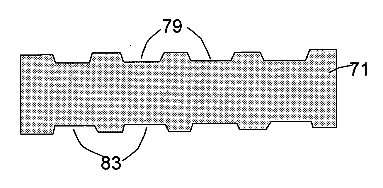
[0020] This invention provides a fuel cell flow field plate or bipolar plate having flow channels on faces of the plate, comprising an
electrically conductive polymer composite. In one preferred embodiment, the composite is composed of (A) at least 50% by weight of a conductive filler, comprising at least 5% by weight reinforcement fibers, expanded graphite platelets, graphitic nano-fibers, and / or carbon nano-tubes (this at least 5% is based on the total weight f the composite); (B)
thermoplastic at 1 to 49.9% by weight; and (C) thermoset binder at 0.1 to 10% by weight; wherein the sum of the conductive filler weight %,
thermoplastic weight % and thermoset binder weight % equals 100% and the bulk electrical conductivity of the flow field or bipolar plate is at least 100 S / cm and, preferably, at least 200 S / cm. The thermoset binder resin has the
advantage that it can be quickly cured so as to hold the reinforcement elements together, typically without a need to be heated to a high temperature and then cooled down slowly. The resulting preform is very easy to
handle during subsequent molding operations. The thermoset resin is selected from the group consisting of
unsaturated polyester resins, vinyl esters, epoxies, phenolic resins,
polyimide resins, bismaleimide resins,
polyurethane resins, and combinations thereof. A fast-curing or
ultraviolet-curable resin is preferred.
[0021] The conductive filler comprises a conductive material selected from the group consisting of graphite
powder, carbon / graphite fibers,
metal fibers, carbon nano-tubes, graphitic nano-fibers, expanded graphite platelets, carbon blacks,
metal particles, and combinations thereof. This filler may comprise some non-conductive fibers, such as glass fibers and polymer fibers, for the purpose of reinforcing or strengthening the composite without significantly reducing the electrical conductivity. Preferably, the thermoset binder is at 0.1 to 5% by weight and the
thermoplastic is at 10 to 40% by weight. This composition is such that reinforcement fibers, carbon nano-tubes, graphitic nano-fibers, and / or expanded graphite platelets (those reinforcement elements having a high
aspect ratio, such as a high length / thickness ratio or length /
diameter ratio) form an overlapping, contiguous-strand backbone structure. Preferably, these high aspect-ratio elements are bonded together by the thermoset resin binder, or a combination of the thermoset binder and thermoplastic, to form a shape-retaining backbone. This shape-retaining backbone or “preform” makes it easily handleable for subsequent molding,
embossing and / or
stamping operations to form a flow field or bipolar plate.
[0022] In another preferred embodiment, the composite comprises an electrically
conductive polymer composite having: (A) at least 50% by weight of a conductive filler, comprising at least 5% by weight reinforcement fibers, expanded graphite platelets, graphitic nano-fibers, and / or carbon nano-tubes; (B) a polymer matrix material at 1 to 49.9% by weight; and (C) a polymer binder at 0.1 to 10% by weight; wherein the sum of the conductive filler weight %, polymer matrix material weight % and polymer binder weight % equals 100% and the bulk electrical conductivity of the flow field plate or bipolar plate is at least 100 S / cm. In this case, the polymer matrix material is not a pure thermoplastic; instead, it may comprise a material selected from a thermoset resin, an interpenetrating network, a semi-interpenetrating network, an
elastomer, or a combination thereof. The polymer binder can be advantageously selected from thermoset resins, but it does not have to be a thermoset resin. For instance, it can be a thermoplastic provided that heating and melting the thermoplastic to a high temperature (e.g., >200° C.) is not required. It is convenient to have a binder comprising a
water soluble polymer.
Vaporization of water allows the polymer to precipitate and bond to the reinforcement elements quickly. In one further preferred embodiment, the plate has a major surface having a
skin layer less than 100 μm in thickness and having a polymer
volume fraction less than 20%, preferably less than 10%. In other words, the
skin layer is preferably composed of at least 80% conductive filler and more preferably at least 90% conductive filler. Such a
skin layer prevents the formation of a resin-rich skin layer that otherwise has a high, dominating electrical resistance.

