Radial tire for airplane

a technology for airplanes and tires, applied in aircrafts, transportation and packaging, yarn, etc., can solve the problems of poor heat shrinking property of aramid fiber cords, difficult to completely correct a slight non-uniform strength between the cords, and difficult to equalize the tension of belt cords in the pressure test for measuring the safety ratio of tires

Inactive Publication Date: 2007-09-27
BRIDGESTONE CORP
View PDF2 Cites 9 Cited by
  • Summary
  • Abstract
  • Description
  • Claims
  • Application Information

AI Technical Summary

Benefits of technology

[0028] As the polyketone fiber cord satisfying the equations (I) and (II) can be used a polyketone fiber cord substantially having a repeated unit represented by the following formula (III):
[0029] In a starting polyketone for the polyketone fiber cord, ketone groups may be partly bonded to each other or moieties derived from the unsaturated compound may be bonded to each other, but it is preferable that a ratio of alternate arrangement of the moiety derived from the unsaturated compound and the ketone group is not less than 90% by mass, more preferably not less than 97% by mass, most preferably 100% by mass.
[0030] As the unsaturated compound forming A in the formula (III) is most preferable ethylene. Also, there may be an unsaturated hydrocarbon other than ethylene such as propylene, butene, pentene, cyclopentene, hexene, cyclohexene, heptene, octene, nonene, decene, dodecene, styrene, acetylene, allene or the like; a compound containing an unsaturated bond such as methyl acrylate, methyl metacrylate, vinyl acetate, acrylamide, hydroxyethyl methacrylate, undecenic acid, undecenol, 6-chlorohexene, N-vinylpyrolidone, diethylester of sulnylphosphric acid, sodium styrenesulfonate, sodium allylsulfonate, vinylpyrolidone, vinyl chloride or the like; and so on.
[0031] As the polymerization degree of the polyketone, it is preferable that a limit viscosity (η) defined by the following equation (IV): [η]=⁢limC→0⁢(T-t)(t·C)
[0032] As a method of forming polyketone fiber are preferable (1) a method of subjecting an undrawn fiber to a multi-stage heat drawing in which a final drawing at the multi-stage heat drawing step is carried out at specified temperature and draft ratio and (2) a method of subjecting an undrawn fiber to heat drawing and then quenching under a high tension. By forming the polyketone fiber through the method (1) or (2) can be obtained desirable filaments suitable for the production of the polyketone fiber cord.
[0033] The method of spinning the polyketone undrawn fiber is not particularly limited, but may adopt the conventionally known methods. Concretely, there are mentioned a wet spinning method using an organic solvent as disclosed in JP-A-H02-112413, JP-A-H04-228613 and JP-A-H04-505344, and a wet spinning method using an aqueous solution of zinc salt, calcium salt, thiocyanate, iron salt or the like as disclosed in WO99 / 18143, WO00 / 09611, JP-A-2001-164422, JP-A-2004-218189 and JP-A-2004-285221. Among them, the wet spinning method using the aqueous solution of the salt is preferable.

Problems solved by technology

On the other hand, it is imposed from airplane makers to satisfy the demand of significantly reducing the tire weight, and hence the establishment between the tire performances and the weight reduction is an important issue in the tire design.
However, aramid fiber cord widely used as a constitutional member of the tire is poor in the heat shrinking property.
Therefore, it is difficult to completely correct a slight non-uniformity of the strength between the cords generated in the shaping of the tire at a tire vulcanization step, and hence it is difficult to equally apply tension to belt cords in the pressure test for measuring the safety ratio of the tire.
Thus, the above cord property in the conventional tire product obstructs the weight reduction of the tire.
Also, standing wave is caused in the vicinity of the sidewall during the high-speed rotation of the tire to promote heat generation in the side portion, which considerably damages the durability of the tire.
In the belt, however, it is difficult to uniformly bear the tension between t he cords as previously mentioned, so that it i s also required to arrange the excessive number of the members for preventing the standing wave.

Method used


Image

  • Radial tire for airplane
  • Radial tire for airplane
  • Radial tire for airplane

Examples


Embodiment Construction

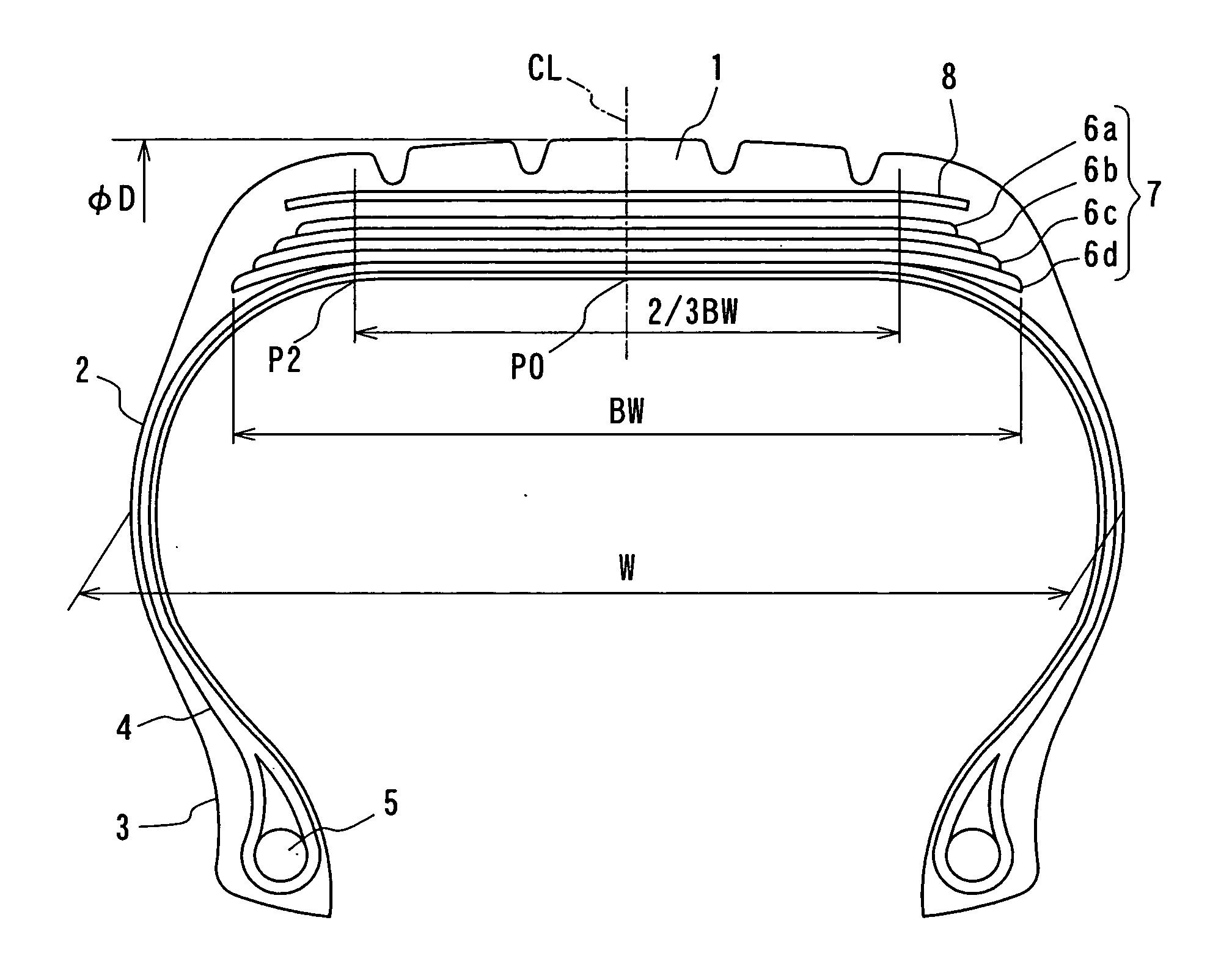
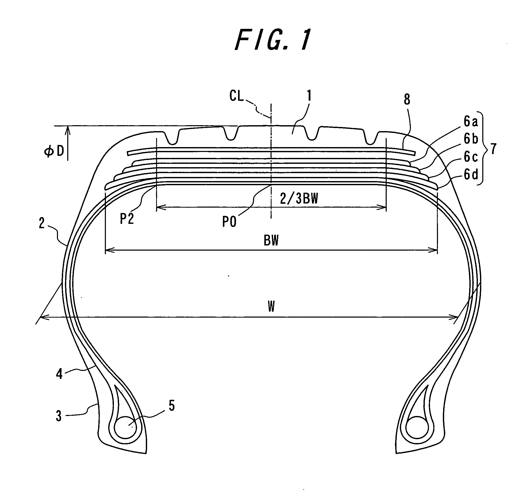
[0018]FIG. 1 is a diagrammatically cross-section view of a radial tire for airplane according to the invention. In FIG. 1, numeral 1 is a tread portion, numeral 2 a pair of sidewall portions continuously extending inward from side ends of the tread portion 1 in a radial direction, and numeral 3 a bead portion continuously arranged at an inner peripheral side of each of the sidewall portion 2.

[0019] Also, a radial carcass 4 comprised of at least one carcass ply is toroidally extended between both the bead portions 3. The radial carcass 4 reinforcing the portions 1, 2 and 3 is arranged so that each side portion thereof is wound around a circular ring-shaped bead core 5 embedded in the bead portion 3 from inside toward outside.

[0020] On an outer periphery of a crown portion of the radial carcass 4 is disposed a belt 7 comprised of plural belt layers 6. Moreover, a belt protection layer 8 may be arranged on an outside of the belt in the radial direction.

[0021] In the invention, when ...


PUM

PropertyMeasurementUnit
angleaaaaaaaaaa
lengthaaaaaaaaaa
viscosityaaaaaaaaaa

Abstract

A radial tire for airplane comprises a pair of bead cores, a radial carcass, and a belt disposed on an outer periphery of a crown portion of the radial carcass and comprised of plural belt layers each containing organic fiber cords, in which a total strength in a circumferential direction over a full width of the belt Tbelt(N) satisfies Tbelt/WD≧1.5×106 when an outer diameter of the tire is D (m) and a width of the tire is W (m), and at least one layer of the belt layers is constituted with an organic fiber cord spirally winding at an angle of approximately 0° with respect an equatorial plane of the tire and satisfying the following equations (I) and (II):
σ≧−0.01E+1.2   (I)
σ≧0.02   (II)
(wherein σ is a heat shrinkage stress at 177° C. (cN/dtex) and E is an elastic modulus at 25° C. under a load of 49 N (cN/dtex)).

Description

BACKGROUND OF THE INVENTION [0001] 1. Field of the Invention [0002] This invention relates to a radial tire for airplane, and more particularly to an airplane radial tire capable of establishing the high-speed durability and the weight reduction of the tire. [0003] 2. Description of the Related Art [0004] The radial tire for airplane is defined to satisfy a basic internal pressure as very high as more than 10 atmospheric pressure as an official standard but also the reinforcing member for the tire is required to have a resistance top pressure corresponding to 4 times of the basic internal pressure in order to satisfy the requirement of higher reliability. In the belt of the tire, therefore, the resistance to pressure is satisfied by laminating many plies each comprised of organic fiber cords. On the other hand, it is imposed from airplane makers to satisfy the demand of significantly reducing the tire weight, and hence the establishment between the tire performances and the weight r...

Claims


Application Information

Patent Timeline
Patent Type & Authority Applications(United States)
IPC IPC(8): B60C9/00
CPCB60C9/2204Y10T152/10783B60C2200/02B60C9/28
Inventor YANO, TAKESHIISHIZAKI, SUSUMU
Owner BRIDGESTONE CORP
Why Eureka
Try Eureka