

Separator for fuel cells
a fuel cell and separator technology, applied in the field of separators for fuel cells, can solve the problems of cracks at the interface between metal materials and metal thin films, the failure of unit cells to use these components, and the worsening of the assembly work efficiency of unit cells using these components, so as to facilitate the assembling of unit cells
- Summary
- Abstract
- Description
- Claims
- Application Information
AI Technical Summary
Benefits of technology
Problems solved by technology
Method used
Image

Examples
example 1
[0101] A 0.8 mm thick SUS304 (80 mm×80 mm) provided as a metal plate material was degreased on the surface.
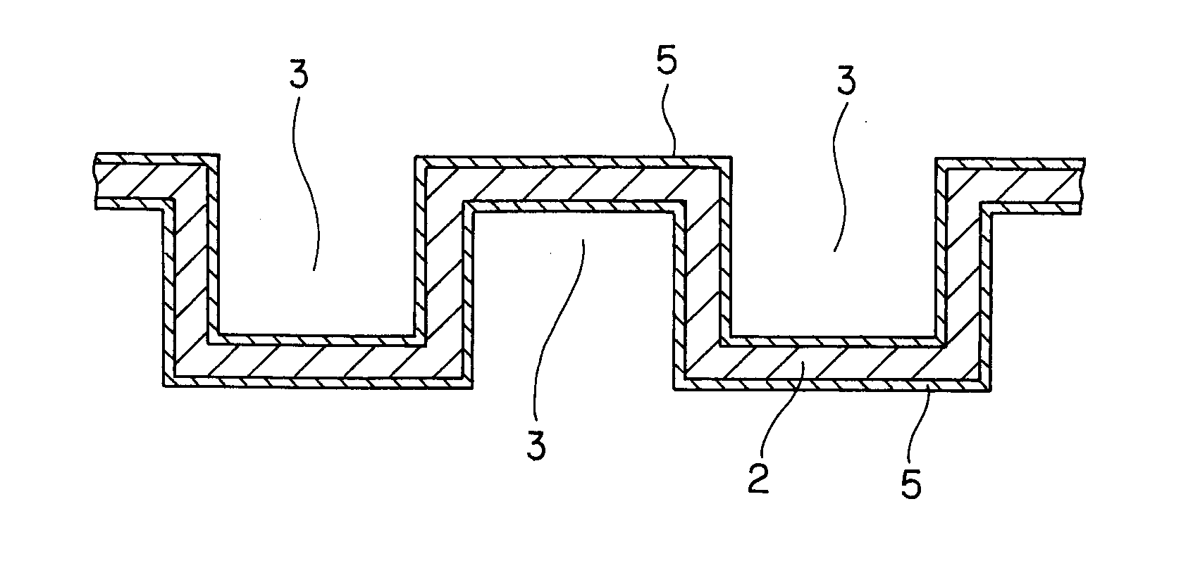
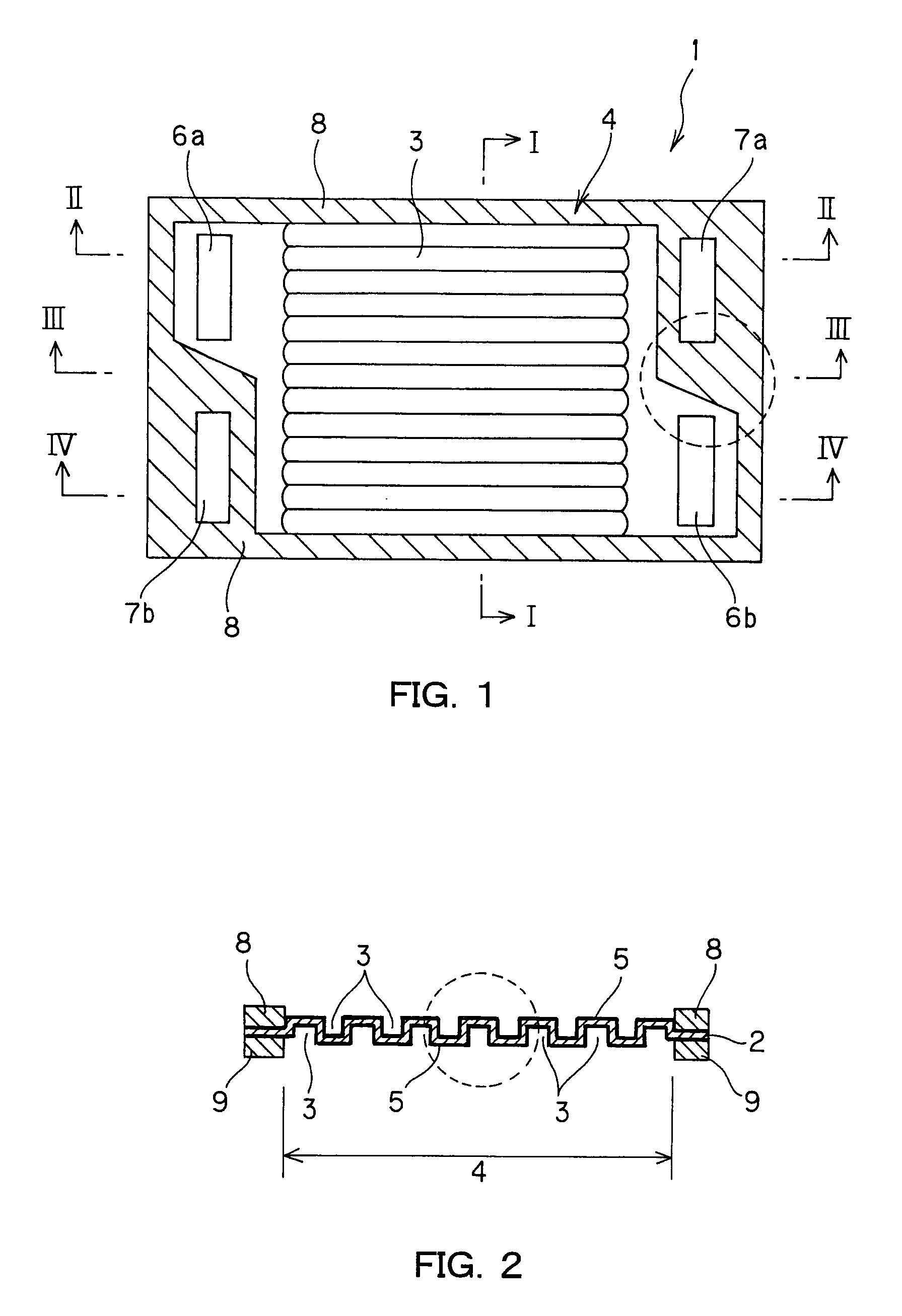
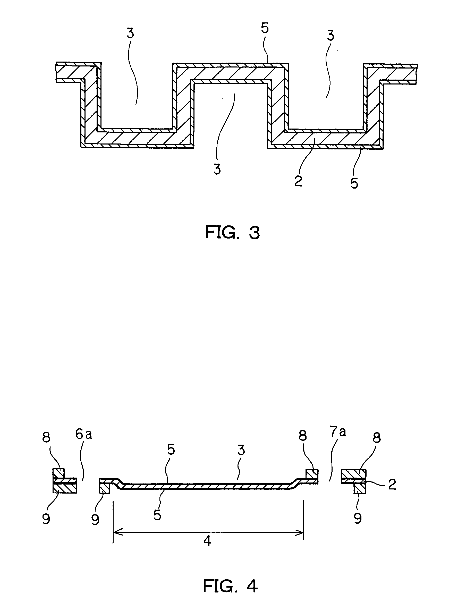
[0102] Then, the SUS304 was pressed to prepare such a metal substrate having grooves as shown in FIGS. 1-6. In both surfaces of the metal substrate, 70 grooves per surface, each of 800 μm in width and 80 mm in length, were alternately located at a pitch of 1,200 μm. Each groove had a depth of 600 μm.
[0103] Then, the metal substrate was pretreated with a hydrochloric acid solution (9 parts of water plus 1 part of 35% hydrochloric acid added to it) of 50° C., followed by water rinsing.
[0104] Then, an electrically conductive material carbon black (Vulcan XC-72 made by Cabot Co., Ltd.) was dispersed in an epoxy electrodeposition solution in an amount of 75% by weight relative to solid resin matter to obtain an electrodeposition solution.
[0105] While that electrodeposition solution was held at 20° C. under agitation, the aforesaid metal substrate was dipped in it for a 1-minute ...
example 2
[0111] An aluminum alloy (A5052P) of 80 mm×80 mm in size and 0.8 mm in thickness provided as a metal plate material was degreased on the surface.
[0112] Then, a dry film resist (made by Nichigo-Morton Co., Ltd) was laminated on each surface of that aluminum alloy to form a 35 μm thick photosensitive resist layer. Thereafter, exposure (a 15-second irradiation with light from a 5 kW mercury lamp) was implemented via a photomask for the formation of grooves, and development (spraying of a 2% sodium hydrogencarbonate aqueous solution of 30° C.) was then carried out to form a resist.
[0113] Then, an aqueous solution of ferric chloride heated to 45° C. was sprayed onto the aluminum alloy from both its sides via the aforesaid resist for half etching down to the predetermined depth. Thereafter, the resist was removed off using a 5% sodium hydrogencarbonate aqueous solution, and the aluminum alloy washed to thereby obtain a metal substrate having a 1-mm wide, 0.3-mm deep groove of almost sem...
example 3
[0121] A copper alloy (copper-tin-chromium) of 80 mm×80 mm in size and 0.8 mm in thickness provided as a metal plate material was degreased on the surface.
[0122] Then, a photosensitive material (a mixture of casein and ammonium bichromate) was formed by dip coating on each surface of that copper alloy to form a 2 μm thick coating film. Thereafter, exposure (a 60-second irradiation with light from a 5 kW mercury lamp) was implemented via a photomask for the formation of grooves, and development (spraying of warm water of 40° C.) was then carried out to form a resist.
[0123] Then, an aqueous solution of ferric chloride heated to 70° C. was sprayed onto the copper alloy from both its sides by way of the aforesaid resist for half etching down to the predetermined depth. Thereafter, the resist was removed off using a caustic soda aqueous solution of 80%, and the copper alloy washed to thereby obtain a metal substrate having a 1-mm wide, 0.3-mm deep groove of almost semi-circular shape i...
PUM
| Property | Measurement | Unit |
|---|---|---|
| Electrical conductivity | aaaaa | aaaaa |
| Electrical resistance | aaaaa | aaaaa |
| Area | aaaaa | aaaaa |
Abstract
Description
Claims
Application Information