

Fluorescent Material, a Method of Manufacturing the Fluorescent Material, a Radiation Detector Using the Fluorescent Material, and an X-Ray Ct Scanner
a technology of fluorescent materials and x-ray ct scanners, which is applied in the direction of inorganic chemistry, rare earth metal compounds, crystal growth processes, etc., can solve the problems of low detection efficiency of x-ray, electrode plates vibrating, and low sensitivity, so as to achieve high sensitivity, high fluorescence intensity, and weak afterglow
- Summary
- Abstract
- Description
- Claims
- Application Information
AI Technical Summary
Benefits of technology
Problems solved by technology
Method used
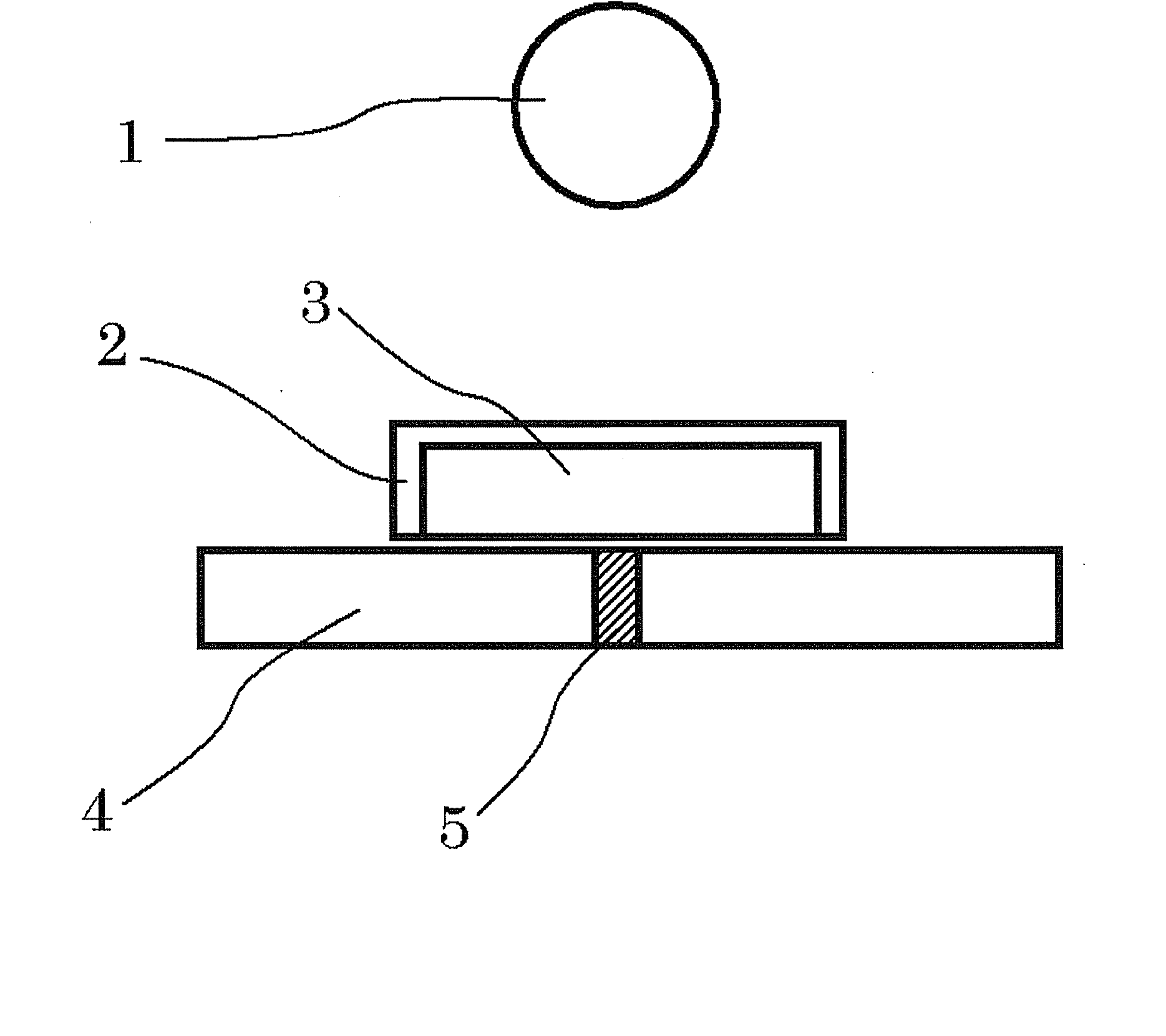
Image

Examples
1st embodiment
A 1st Embodiment
[0061] A fluorescent material concerning a 1st embodiment has weak afterglow, and it has high fluorescence intensity by making especially optical transmittance high. This fluorescent material contains cerium (Ce) as an activator. It is a fluorescent material with the garnet structure which contained gadolinium (Gd), aluminum (aluminum), gallium (Ga), and oxygen (O) at least. With atomic number ratios, Ga / (Gd+Ga+Al+Ce) is 0.2-0.3, Al / (Gd+Ga+Al+Ce) is 0.35-0.4, and Ce / (Gd+Ga+Al+Ce) is 0.0005-0.006. And the fluorescent material is single crystal. If composition of Gd, Ga, and Al which constitute a host material is outside of said range, sufficient fluorescence intensity cannot be obtained. Deviation from the stoichiometric composition of the garnet structure (Gd1−zCez)3(Al1−uGau)5O12, makes defect levels due to nonstoichiometric defect. It is supposed that this defect levels serve as energy levels in phonon transition without luminescence. On the other hand, when the co...
2nd embodiment
A 2nd Embodiment
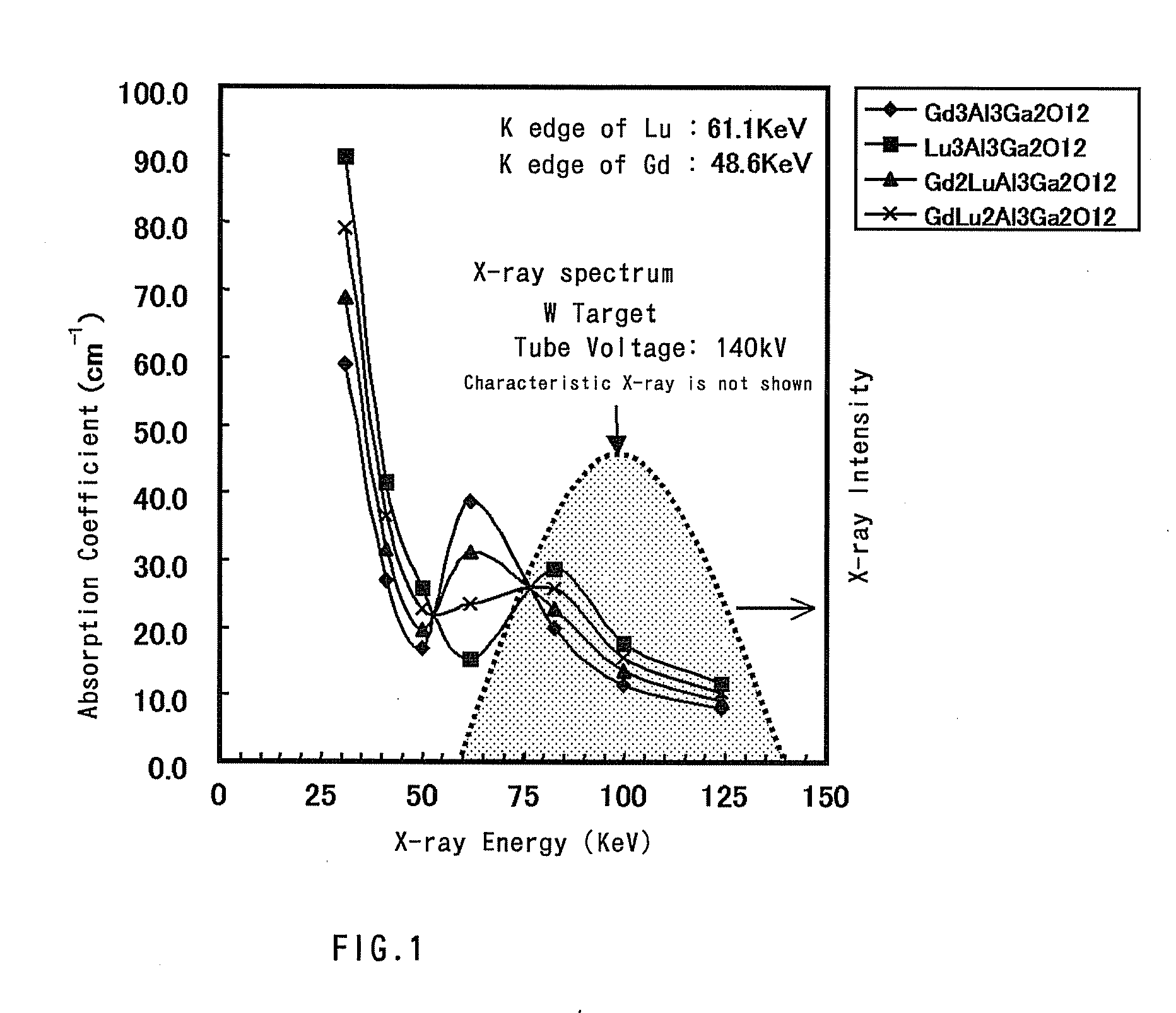
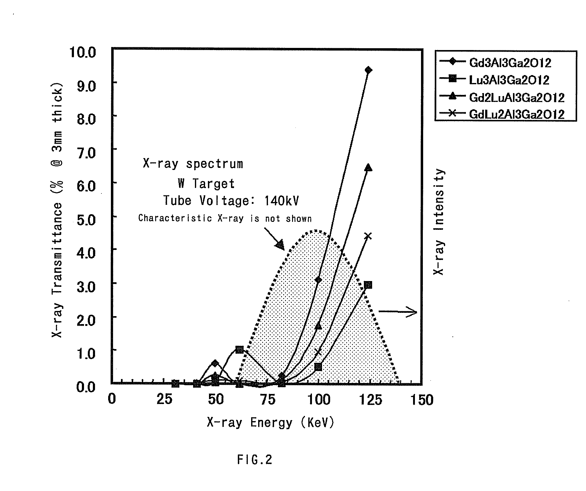
[0071] In a fluorescent material concerning a 2nd embodiment, afterglow is weak and the fluorescence intensity is raised by raising X-ray absorption coefficient. This material is a fluorescent material with garnet structure containing cerium (Ce) as the activator, and also containing gadolinium (Gd), lutetium (Lu), aluminum (aluminum), gallium (Ga), and oxygen (O) at least, and its general formula is expressed with Gd3−p−qLupCeqAlrGa5−rO2, here, 0.1≦p≦3.0, 0.001≦q≦0.05, and 2≦r≦4. In the garnet structure shown in (Gd, Lu, Ce)3(Al, Ga)5O12, as deviation from stoichiometry becomes large, on composition of Gd, Lu, Ga, and Al, which constitute a host material, fluorescence intensity will be decreased. Because nonstoichiometric defects will be generated in the crystal and the defect will work as a center of electron transition without fluorescence in this case. High fluorescence intensity cannot be obtained, when the composition of Ce, which is an activator, is out of abo...
3rd embodiment
A 3rd Embodiment
[0076] A fluorescent material of 3rd embodiment has both high fluorescence intensity and weak afterglow. This material is a fluorescent material with garnet structure containing cerium (Ce) as the activator, and also containing gadolinium (Gd), aluminum (Al), gallium (Ga), and oxygen (O), and lutetium (Lu) or yttrium (Y). And its general formula is expressed with (Gd1−x−zLxCez)3+a(Al1−uGau)5−aO12, here, L is Lu or / and Y, 0<a≦0.15, 0<x<1.0, 0.0003≦z≦0.0167 (here, x+z<1.0), 0.2≦u≦0.6. This fluorescent material is characterized by setting the composition shifted the composition in garnet structure from stoichiometry (a=0) including Lu or / and Y. Here, the element (Gd, L, Ce) located at C site (eightfold coordination) is in excess of stoichiometry, as 0<a. And the element (Al, Ga) located at A site (sixfold coordination) and D site (fourfold coordination), is decreased instead. The fluorescent material of the 2nd embodiment mentioned above corresponds to the case where a=...
PUM
| Property | Measurement | Unit |
|---|---|---|
| wavelength | aaaaa | aaaaa |
| thickness | aaaaa | aaaaa |
| thickness | aaaaa | aaaaa |
Abstract
Description
Claims
Application Information