Dye-Sensitized Photoelectic Conversion Devices

a technology of photoelectic conversion and dye, which is applied in the direction of sustainable manufacturing/processing, other chemical processes, and final product manufacturing, etc., can solve the problems of high cost of dyes themselves, high energy and cost to produce, and difficult general use, etc., and achieve high stability and conversion efficiency

Inactive Publication Date: 2008-03-20
NIPPON KAYAKU CO LTD
View PDF20 Cites 24 Cited by
  • Summary
  • Abstract
  • Description
  • Claims
  • Application Information

AI Technical Summary

Benefits of technology

[0036] In the dye-sensitized photoelectric conversion devices of the present invention, dye sensitization in high stability and conversion efficiency is carried out by using o...

Problems solved by technology

These solar cells, however, require high energy and cost to produce, and thus there was a problem that it was difficult to use generally.
In the dye-sensitized type photoelectric conversion devices now under development, however, the ruthenium-based complexes are used as sensitizing dyes to obtain the photoelectric conversion devices with high conversion efficiency;...

Method used


Image

  • Dye-Sensitized Photoelectic Conversion Devices
  • Dye-Sensitized Photoelectic Conversion Devices
  • Dye-Sensitized Photoelectic Conversion Devices

Examples


synthesis example 1

[0097] Into 20 parts of ethanol, 5 parts of the compound (240) to be described below and 4.2 parts of methyl cyanoacetate were dissolved, and 0.05 parts of anhydrous piperazine was added thereto. After subjecting the solution to a reaction for 2 hours under reflux, it was cooled to separate out orange crystal, which was filtered, washed with water and dried. The resultant crystal was added into 50 ml of an ethanol solution of 5% potassium hydroxide, and subjected to a reaction for 1 hour under reflux. The reaction solution was poured into 100 ml of water, and further an aqueous solution of 10% hydrochloric acid was added until pH became 6. The separated-out crystal was filtered, washed with water, dried and purified with column chromatography. By further recrystallization from chloroform, 5.3 parts of the compound (21) was obtained as orange crystal.

[0098]λMax (EtOH: 402 nm)

[0099] 1H-NMR (PPM:d6-DMSO):6.94(d.arom.2H),7.06(m.arom.8H),7.23(m.arom.5H), 7.34(t.arom.4H), 7.44(t.arom.2H...

synthesis example 2

[0102] By similar processing as in Synthesis Example 1 except that 5.2 parts of the compound (241) to be described below was used instead of the compound (240) in Synthesis Example 1, 7 parts of the compound (128) was obtained as orange crystal.

[0103]λmax (EtOH: 422 nm)

synthesis example 3

Synthesis of the Compound (168)

[0104] Into 20 parts of ethanol, 5 parts of the compound (241) and 4.2 parts of rhodanine-3-acetic acid were added, and 0.05 parts of anhydrous piperazine was added thereto. After subjecting the solution to a reaction for 2 hours under reflux, it was cooled to separate out an orange crystal, which was filtered, and washed with water. By further recrystallization from ethanol, 6.3 parts of the compound (168) was obtained as orange brown crystal.

[0105]λmax (EtOH: 496 nm)


PUM


Abstract

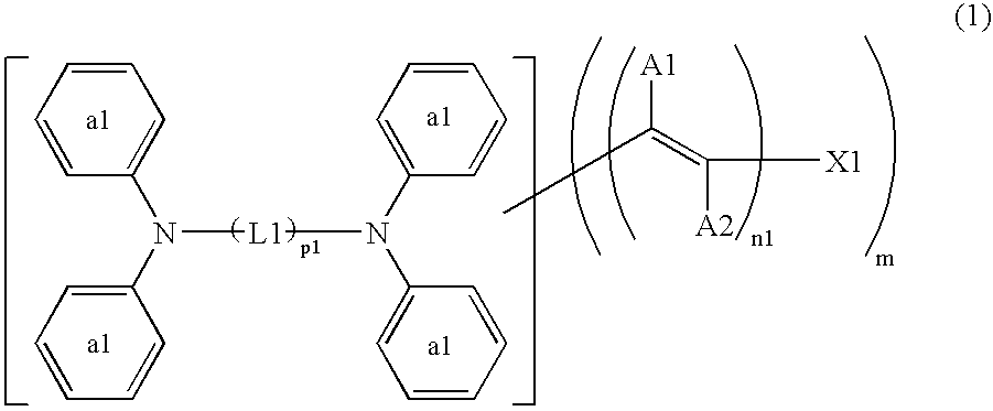
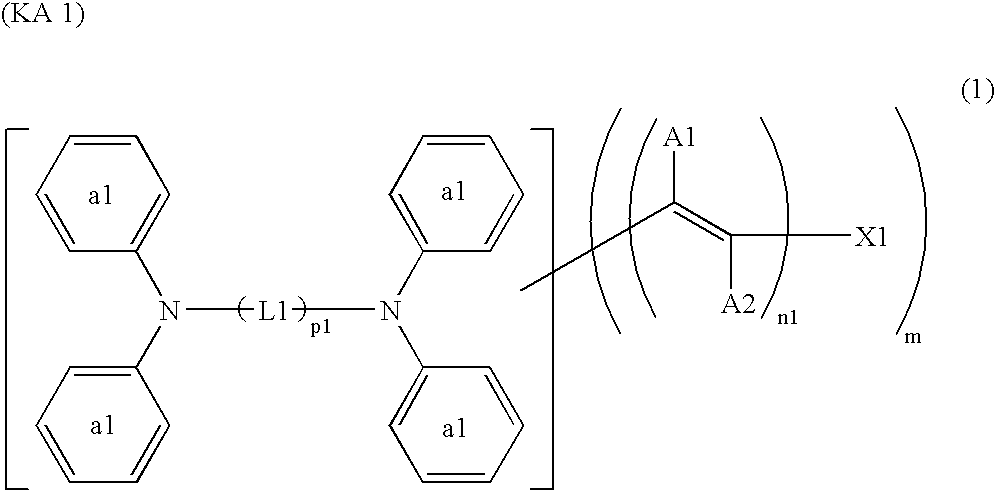
The present invention relates to photoelectric conversion devices, characterized by using oxide semiconductor particles sensitized with a methine dye represented by the Formula (1):
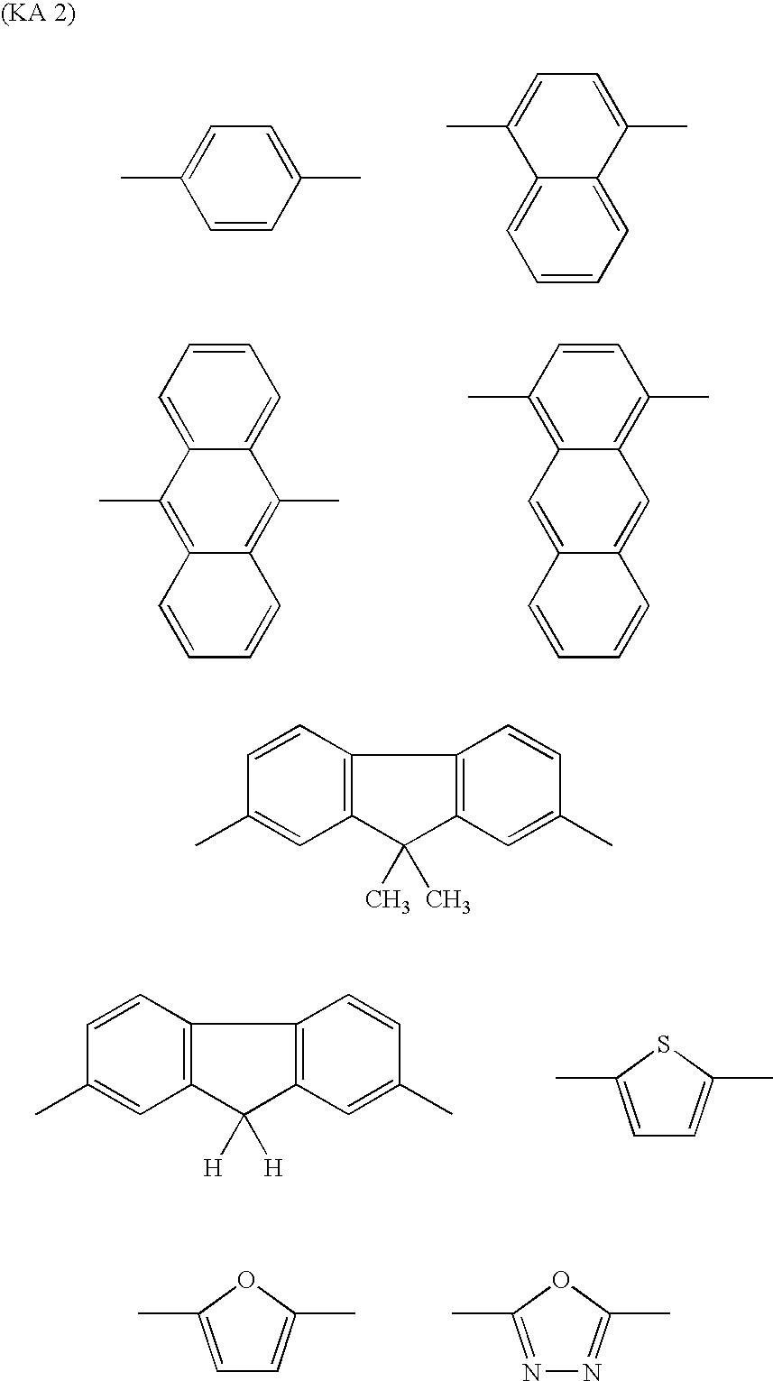
(in the Formula (1), m represents 1 to 4; n1 represents 1 to 7; p1 represents 1 to 4; X1 represents an optionally substituted aromatic residue, an optionally substituted aliphatic hydrocarbon residue, a cyano group, a phosphoric acid group, a sulfonic acid group, or a carboxyl group, a carbonamide group, and the like; L1 represents an optionally substituted aromatic residue and the like; A1 and A2 each independently represent an optionally substituted aromatic residue, a hydroxyl group, a phosphoric acid group, a cyano group, a hydrogen atom, a halogen atom and the like; the ring a1 has 1 or a plurality of halogen atoms, amide groups, hydroxyl groups, cyano groups, nitro groups, alkoxy groups, acyl groups and the like.), and solar cells made by using the same. The devices and the cells are characterized by relatively low cost, high stability, and high photoelectric conversion efficiency.

Description

TECHNICAL FIELD [0001] The present invention relates to the photoelectric conversion devices sensitized with an organic dye, and the solar cells made by using the same, in detail, relates to the photoelectric conversion devices characterized by using the oxide semiconductor particles sensitized with a methine dye having a specific skeleton, and the solar cells made by utilizing the same. BACKGROUND ART [0002] The solar cells utilizing sunlight have been drawn attention as an energy resource to replace a fossil fuel such as petroleum, coal and natural gas or the like. At present, an efficiency enhancement is actively studied on silicon solar cells using crystalline or amorphous silicon, or compound semiconductor solar cells or the like using gallium, arsenic or the like. These solar cells, however, require high energy and cost to produce, and thus there was a problem that it was difficult to use generally. [0003] In addition, the photoelectric conversion devices using dye-sensitized ...

Claims


Application Information

Patent Timeline
IPC IPC(8): C09K3/00
CPCC09B23/0091Y02E10/549H01G9/2031H01G9/2059H01L51/0053H01L51/0054H01L51/0059H01L51/006H01L51/0064H01L51/0068H01L51/0072H01L51/422H01M14/005Y02E10/542C09B23/14Y02P70/50H10K85/621H10K85/652H10K85/622H10K85/655H10K85/633H10K85/631H10K85/6572H10K30/15H01L31/04C09B23/00
Inventor SHIGAKI, KOICHIROINOUE, TERUHISA
Owner NIPPON KAYAKU CO LTD
Why Eureka
Try Eureka