Eureka AIR delivers breakthrough ideas for toughest innovation challenges, trusted by R&D personnel around the world.

System and Method for Biological Wastewater Treatment and for Using the Byproduct Thereof

a biological wastewater and treatment system technology, applied in the field of biological wastewater treatment systems, systems and methods for treating wastewater and using the byproducts of such treatment, can solve the problems of inability to meet the needs of biological treatment, etc., to achieve the effect of facilitating the growth of bacteria and facilitating the following biological reaction

Active Publication Date: 2008-06-12
LIMCACO CHRISTOPHER A
View PDF17 Cites 36 Cited by
  • Summary
  • Abstract
  • Description
  • Claims
  • Application Information

AI Technical Summary

Benefits of technology

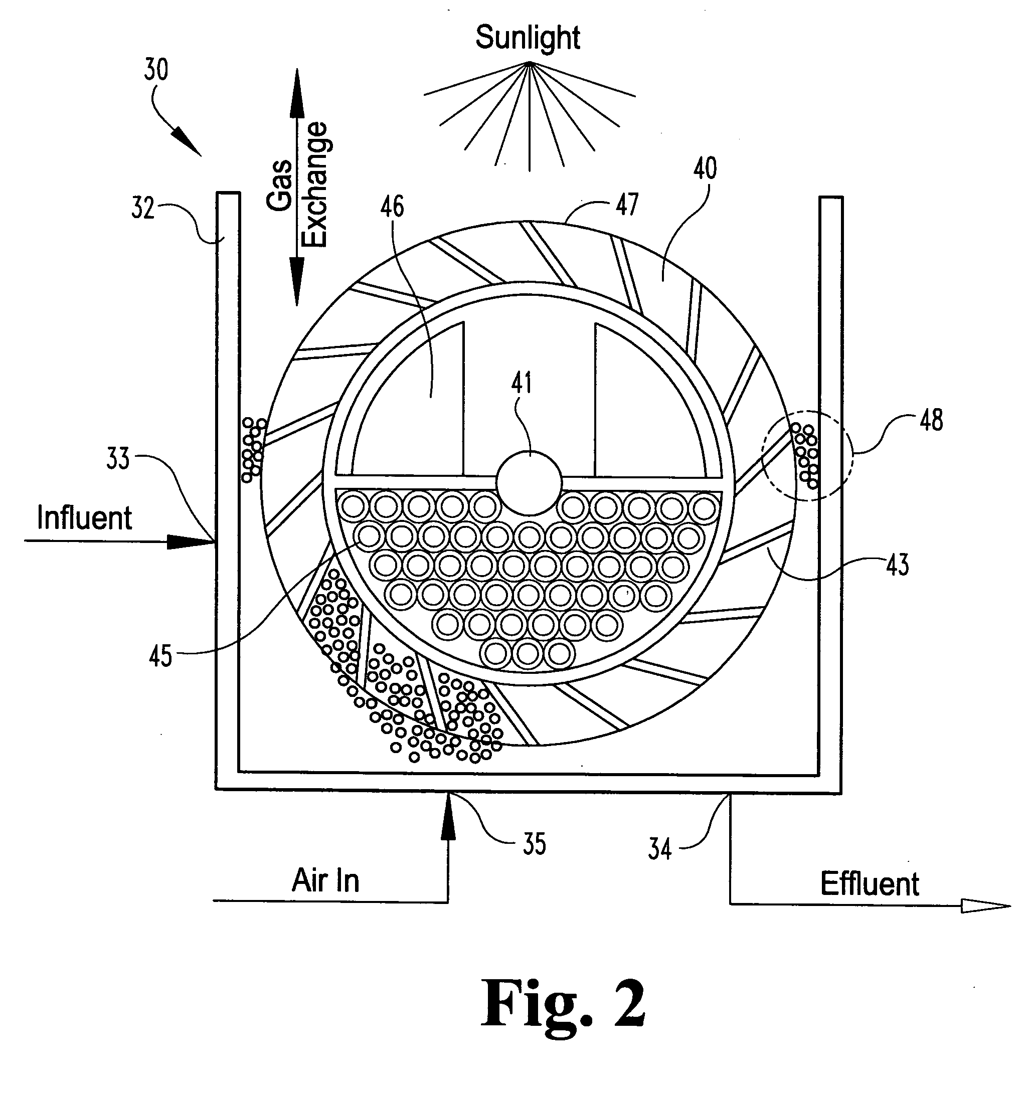
[0020]In one embodiment, the secondary treatment tank includes a rotating wheel construction that provides surfaces for colonization by algae. This rotating wheel system facilitates the following biological reaction occurring by photosynthesis:CO2+2H2O+Solar Energy→(CH2O)x+O2+H2Owhere (CH2O)x represents the organic matter fixed in the algal biomass. The inventive system capitalizes on a beneficial symbiosis between algae and bacteria which results in a cost effective method of producing algae. The bacteria rely on the presence of O2 produced by the algae and the algae rely on the CO2 produced by the bacteria. The growth of bacterial and algal colonies in the secondary treatment tank results in a reduction of BOD (biochemical oxygen demand) from the wastewater source, as well as a reduction in suspended solids, nitrogen, phosphorous, and other nutrients in the discharged effluent to readily meet the discharge limitations established by regulatory agencies. Since the algae uses solar energy in its photosynthetic uptake of nutrients; the rotating wheel of the present system is intentionally exposed to sunlight to take advantage of this source of free energy. The net effect is an efficient environment for the production of bacterial and algal bio-solids found in no other system used to treat wastewater.
[0021]In certain embodiments, the rotating wheels are rotated individually by injecting air from air pumps beneath each wheel. The use of injected air to drive the rotating wheels eliminates the need for mechanical drive mechanisms which have the potential to fail as biomass accumulates on the surface of the rotating wheel. The rotation speed of the wheels is regulated depending on the depth of water in each wheel compartment. The injected air also serves to add O2 to the aqueous solution which is necessary for biological processes employed by both bacterial and algal communities in the tank to uptake nutrients. Additionally, the turbulence produced by the injected air in the tank causes solids-laden algae to break free and enter the flow of the water passing through the system. Continuous flow through the system carries the free algae particles, as well as any solids collected by the algae, toward the exit point of the system.

Problems solved by technology

The secondary stage of wastewater treatment is notoriously problematic due to the complexity of maintaining large bacterial colonies necessary to biologically treat the wastewater.
Maintaining larger and more complex bacterial colonies has unfortunately manifested itself in more costly and complicated equipment and facilities, with a commensurate increase in mechanical failure and equipment downtime.
Another potential problem is that the bacterial colonies are intended to convert the wastewater contaminants into other presumably less toxic forms, such as methane, nitric oxide and CO2 gases.
These on-site systems had obvious limitations, such as land space, geography and topography, water clarity, etc.
In addition, the on-site systems were prone to algae blooms that would overrun and clog the systems.
These limitations led to the development of the algae raceway in the 1970s.
One significant detriment of the algae raceway is that it requires a large surface area for adequate exposure to sunlight.
In addition, the raceway requires a shallow water level to function, which inherently limits the volume and flow of wastewater that can be treated by any particular raceway facility.
However, these alternative energy sources do not appear to have the near-term capability of satisfying the need for petroleum-type fuels—i.e., gasoline and diesel fuels.
Of course, one significant limitation of this technology is that it is tied to a source of waste CO2.
Another detriment is that this proposed technology requires a large raceway pond, and ultimately a large amount of dedicated land in order to support enough algae to accept the waste CO2 and to produce a meaningful amount of algae for use in making a biofuel.
The large size of the pond also means that the useful “season” may be limited in certain locales and climates due to freezing of the pond.

Method used


Image

  • System and Method for Biological Wastewater Treatment and for Using the Byproduct Thereof
  • System and Method for Biological Wastewater Treatment and for Using the Byproduct Thereof
  • System and Method for Biological Wastewater Treatment and for Using the Byproduct Thereof

Examples


Embodiment Construction

[0036]For the purposes of promoting an understanding of the principles of the invention, reference will now be made to the embodiments illustrated in the drawings and described in the following written specification. It is understood that no limitation to the scope of the invention is thereby intended. It is further understood that the present invention includes any alterations and modifications to the illustrated embodiments and includes further applications of the principles of the invention as would normally occur to one skilled in the art to which this invention pertains.

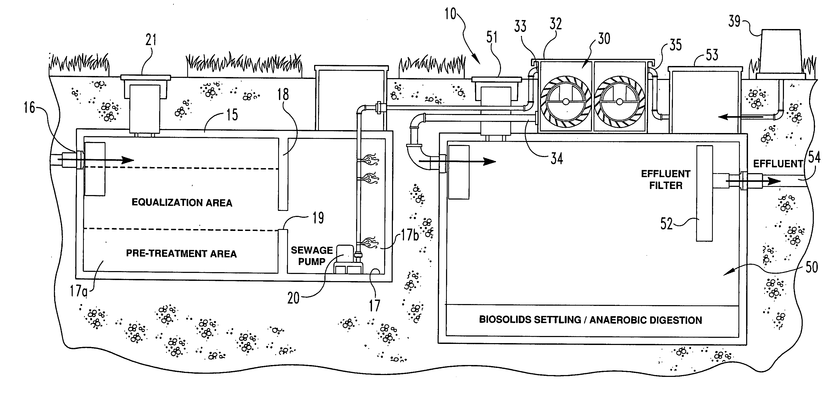
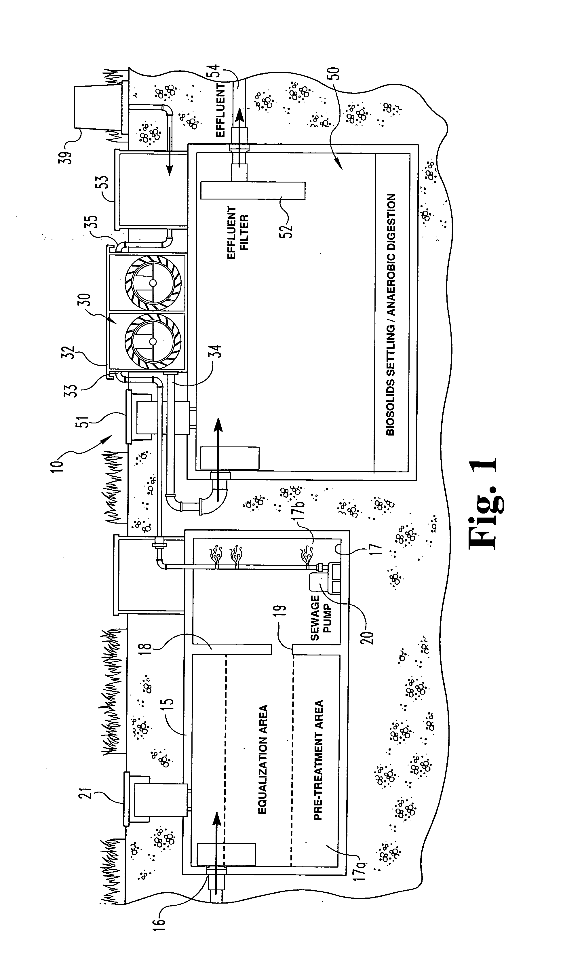
[0037]In one embodiment, a wastewater treatment facility 10 is provided that is adapted for relatively small-scale usage. For instance, the facility 10 shown in FIG. 1 may be used for treatment of residential or commercial wastewater where the wastewater flow rate is as low as about 500 gal / day. A facility of this type may also be used for moderate wastewater flows up to about 25,000 gal / day. The system 10 inclu...


PUM

PropertyMeasurementUnit
shear forcesaaaaaaaaaa
mechanical failureaaaaaaaaaa
surface areaaaaaaaaaaa

Abstract

A wastewater treatment system and process biologically treats wastewater to produce substantially clean water effluent and byproducts. The treatment system includes an array of media wheels that rotate into and out of exposure to sunlight for sustained algae growth. One byproduct is algae removed from the rotating media wheels, which may be provided to other processing facilities to produce, for instance, bio-diesel fuel. Waste CO2 from the processing facility may also be returned to the treatment system for enhanced algae growth. Bacteria is provided to form a symbiotic relationship with the algae, fueled by sunlight to effectively remove toxic materials from the wastewater. Large scale facilities may integrate the treatment systems in a regenerative cycle in which the biomass obtained from the algal colonies is used in a separate facility and byproducts of the operation of the separate facility are used by the treatment system to fuel further algal growth.

Description

REFERENCE TO RELATED APPLICATION[0001]This application is a continuation-in-part of and claims priority to application Ser. No. 11 / 856,175, filed on Sep. 17, 2007, which claims priority to provisional patent application No. 60 / 845,490, filed on Sep. 18, 2006.BACKGROUND[0002]The present invention relates to wastewater treatment systems and processes, and particularly to ecological and biological treatment systems. More specifically, the invention concerns systems and methods for treating wastewater and for using the byproducts of such treatment.[0003]The present invention addresses two critical environmental needs—efficient treatment of wastewater from a variety of sources and development of “green” and renewable energy sources. Wastewater treatment has grown significantly from its origins for treatment of metropolitan sewage. Environmental protection regulations promulgated in the 1900's require treatment of effluent from industrial concerns prior to drainage into a common waterway....

Claims


Application Information

Patent Timeline
Patent Type & Authority Applications(United States)
IPC IPC(8): C12M1/00C02F3/32C02F3/00
CPCC02F1/76C02F3/082C02F3/32C02F2303/24Y02E50/343C05F7/00C12P5/023C12P7/08C02F2305/06Y02W10/37Y02A40/20Y02E50/30Y02W30/40Y02W10/10
Inventor LIMCACO, CHRISTOPHER A.
Owner LIMCACO CHRISTOPHER A
Why Eureka
Eureka Blog
Learn More