Method of Modifying Liquid Crystal Polymers

a liquid crystal polymer and liquid crystal technology, applied in the field of liquid crystal polymer modification methods, can solve the problems of insufficient increase of polymerization degree before forming, limited improvement of physical strength, and fibers, films and the like to be formed from wet process using solvents, etc., to achieve the improvement of tensile strength and elastic modulus, improve the degree of polymerization, and improve the effect of tensile strength

Active Publication Date: 2009-02-19
LEF TECH
View PDF8 Cites 7 Cited by
  • Summary
  • Abstract
  • Description
  • Claims
  • Application Information

AI Technical Summary

Benefits of technology

[0010]The modified liquid crystal polymers of the present invention (particularly, of the melt-type) are substantially improved in polymerization degree in comparison to conventional liquid crystal polymers and are expected to have crosslinked structures. It has been recognized that appropriate increase in irradiation strength leads to improvement in tensile strength and elastic modulus. In this specification, the term “irradiation strength” has the same meaning as “average output power.”
[0011]Based on this fact, it is conceivable that in a spinning process of liquid crystal polymer fiberization, irradiating polymer in a molten state before being extruded through a spinning nozzle or irradiating fibers in a molten or semi-molten state after being extruded from the nozzle outlet, with an ultra short pulse laser in optimized irradiation conditions, increases polymerization degree and improves physical strength through utilization of the nonthermal photochemical reaction. This method is advantageous in that it does not require a process for increasing polymerization degree by performing solid phase polymerization with heat treatment after spinning, that is, a high-temperature treating process under vacuum as in the conventional methods.
[0012]The modified liquid crystal polymer fibers have a possibility to show improvement in tensile breaking strength and initial Young's modulus and also in bending strength and compressive elastic modulus. As applications of fibers having been improved in this property, for example, use of such fibers instead of steel cords to be used in carcass materials of radial tires for passenger cars, light trucks, and especially large trucks and buses makes it possible to further reduce weight of tires and accordingly improve performance and also improve durability (bending fatigue resistance).
[0013]Moreover, in a film forming process of liquid crystal polymer filming, it is conceivable that physical strength and strength uniformity in both the longitudinal direction and the transverse direction (the machine flow direction (MD) and the direction perpendicular thereto (TD)) are improved by optimally irradiating polymer in a molten state before being extruded through the die or irradiating a film in a molten or semi-molten state after being extruded from the die outlet. Furthermore, this modification method has a possibility of imparting to conventional liquid crystal polymers a property of hardly allowing electromagnetic waves with a high frequency of terahertz (1012 Hertz) range to pass therethrough, it is expected to produce new heat-resistant films excellent in high-frequency dielectric characteristics (low dielectric loss).
[0014]In addition, instead of utilizing a photochemical reaction caused by the ultra-short pulse laser, if a similar modification effect can be obtained by irradiating with optimally designed other types of laser or light source, it is expected that photoconversion efficiency in the modification is further improved.

Problems solved by technology

This type involves a disadvantage that fibers, films and the like have to be formed from the wet process using solvent.
However, viscosity in molten state has to be kept low, and therefore polymerization degree is not increased sufficiently before forming.
Improvement in physical strength is thus limited by comparison with solution-type liquid crystal polymer.
It is although known a method of increasing polymerization degree by performing solid polymerization after forming, it requires high-temperature treatment under vacuum, resulting in high production cost.

Method used


Image

  • Method of Modifying Liquid Crystal Polymers
  • Method of Modifying Liquid Crystal Polymers
  • Method of Modifying Liquid Crystal Polymers

Examples


preparation example

Synthesis of Liquid Crystal Polymer (LCP)

[0050]Into a reaction container equipped with a stirring blade and a distillation tube, 256 parts of 4-hydroxybenzoic acid, 129 parts of 2-hydroxy-6-naphthoic acid and 266 parts of acetic anhydride were charged. The mixture was heated from 40° C. to 145° C. over 1 hour in a nitrogen atmosphere and was held at 145° C. for 0.5 hour. Then, the mixture was heated to 325° C. over 7 hours and subsequently was caused to react at 325° C. for 30 minutes, followed by pressure reduction at 325° C. The pressure was reduced down to 100 torr over 90 minutes, followed by a polymerization reaction at 100 torr. When the reaction was continued for 10 minutes, since the stirring torque had reached a predetermined value, the polymerization vessel was closed tightly and the reaction was stopped by increasing the pressure in the polymerization vessel to 0.1 MPa.

[0051]Then, a valve provided at the bottom of the polymerization vessel was opened and thereby the conte...

example 1

[0057]The LCP synthesized in Preparation Example was molded using an injection molding machine (“UH1000-110” manufactured by Nissei Plastic Industrial Co., Ltd.) at a cylinder temperature of 300° C. to yield an LCP plate of 89 mm in length, 54 mm in width and 0.8 mm in thickness.

[0058]Using a Ti:sapphire laser (wavelength of 780 nm, average output power of 600 mW, frequency of 200 kHz, pulse width of 200 femtoseconds) manufactured by Coherent Co., a femtosecond laser beam was focused onto the surface of the resulting LCP plate (focused area: circular area of about 50 μm in diameter) through an objective lens with a magnification of 5.

[0059]As a result, blue fluorescence (second harmonic generation: SHG) was generated immediately after irradiating and a hole as large as about 10 μm to about 20 μm was formed at an irradiation spot by laser abrasion accompanied by thermal impact. A modified portion was observed around the hole. FIG. 1 is a photograph showing the appearance of the LCP p...

example 2

[0060]To a Labo Plastomill 100C100 manufactured by Toyo Seiki Seisaku-sho Co., Ltd. equipped with a T die having a die width of 150 mm and a compression ratio of 2.0, which is adjusted to a cylinder temperature and die temperature at 300° C., the LCP synthesized in Preparation Example was charged. Then, a film having a thickness of about 50 μm was obtained while winding it at a winding rate of 3 m / min.

[0061]Using an erbium-doped quartz fiber laser (wavelength of 780 nm, average output power of 0.14 mW, frequency of 1 kHz, pulse width of 215 femtoseconds) manufactured by Cyber Laser Co., modification was made to a 6 mm×24 mm area of the LCP film by irradiation with a femtosecond laser at an irradiation rate of 10 μm / pulse (10000 μm / sec).

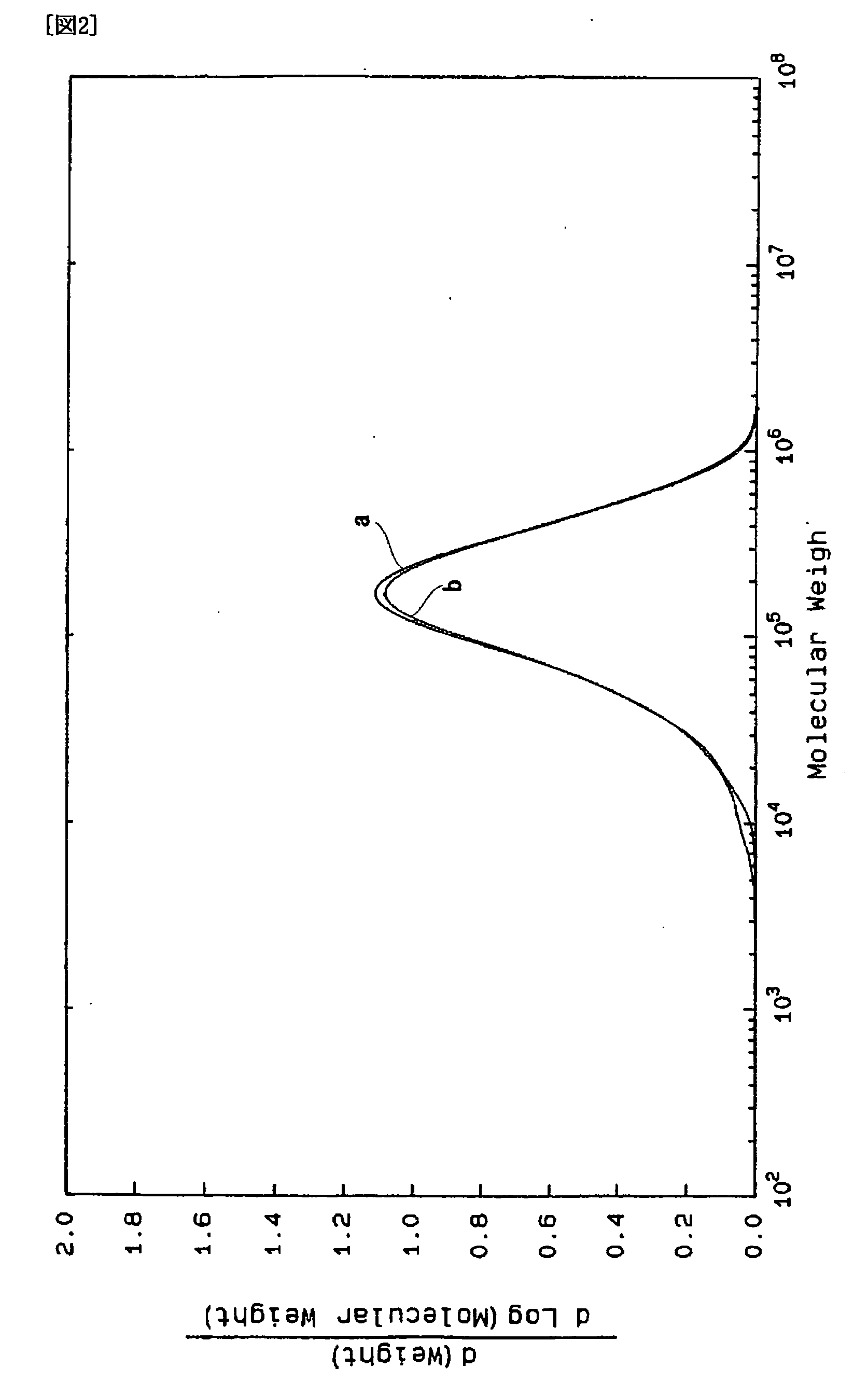
[0062]The sample was subjected to molecular weight distribution measurement by gel permeation chromatography (GPC). FIG. 2 is the spectra showing the results of the GPC measurement of the modified portion and the unmodified portion of the LCP. There i...


PUM

PropertyMeasurementUnit
lengthaaaaaaaaaa
widthaaaaaaaaaa
heat resistanceaaaaaaaaaa

Abstract

A method of modifying liquid crystal polymers, which involves a step of irradiating a liquid crystal polymer with the laser beam having a pulse width of 10−12 seconds or less. Using the invention method, the physical strength of the liquid crystal polymers can be improved as compared with the conventional liquid crystal polymers.

Description

TECHNICAL FIELD[0001]The present invention relates to methods of modifying liquid crystal polymers.BACKGROUND ART[0002]Liquid crystal polymers (LCP) are few in molecular entanglement in liquid state, molecules thereof align along one direction when a shear force is applied to, and solidify with the molecules oriented when they are cooled, so high strength and high elastic modulus is obtained. For example, wholly aromatic polyamide is known as fibers, films and the like having high strength, high elastic modulus and excellent heat resistance. However, this is the solution-type liquid crystal polymer which dissolves in a solvent to form liquid crystal. This type involves a disadvantage that fibers, films and the like have to be formed from the wet process using solvent.[0003]On the other hand, wholly aromatic polyester is the melt-type liquid crystal polymer, which forms liquid crystal in a molten state. This type of liquid crystal polymer has a great advantage of melt-forming such th...

Claims


Application Information

Patent Timeline
Patent Type & Authority Applications(United States)
IPC IPC(8): C08J3/28C08G63/00C08G65/38C08G65/40
CPCB29C71/04B29C2035/0838B29K2105/24C08J7/123C08G63/88C08J3/28C08G63/065C08J7/00C08J7/18
Inventor UENO, RYUZOASAKA, KUNIKAZUHIRAO, KAZUYUKIKANEHIRA, SHINGOKITAYAMA, MASAYA
Owner LEF TECH
Why Eureka
Try Eureka