
System and method for increased cooling rates in rapid cooling of small biological samples

a technology of biological samples and cooling rates, applied in the field of system and method for increasing cooling rates in rapid cooling of small biological samples, can solve the problems of protein and virus crystals easily damaged, protein and virus structure changes that affect protein function, and high variability in protein structure after cryopreservation and thawing, so as to reduce the exposed area and heat transfer, reduce condensation and freezing of water vapor, and reduce the evaporation of liquid cryogens

Active Publication Date: 2009-05-28
CORNELL RES FOUNDATION INC
View PDF24 Cites 31 Cited by
  • Summary
  • Abstract
  • Description
  • Claims
  • Application Information

AI Technical Summary

Benefits of technology

[0023]The present invention addresses this need through provision of a method and devices for rapid cooling of small (10 microliter or smaller) samples to cryogenic temperatures which minimize the thickness of the cold gas layer that forms above the surfaces of liquid cryogens and of solids (e.g., copper) cooled to cryogenic temperatures, replacing this cold gas layer with gas at another, warmer and more uniform temperature at the same or similar pressure. In one preferred method, this is achieved by simply blowing the cold gas layer away. This greatly increases the temperature gradient in the gas immediately above the liquid or solid surface, so that when a small sample moves through the gas toward the surface, most cooling from its initial temperature will occur when it enters the liquid (or when it contacts the solid), not in the gas layer above it, even when it moves at modest speeds. As a result, heat transfer rates during cooling are greatly increased, and the time required to cool the sample between its initial temperature (for example, the ambient temperature far from the surface) and the liquid or solid temperature is dramatically reduced. Preliminary experiments suggest that this very simple method can yield cooling rates for sample speeds perpendicular to the surface of less than 1 m / s and at atmospheric pressure of up to 100,000 K / s, and that are comparable to the highest cooling rates reported for evaporative cooling of micrometer-size water drops in vacuum and of drops sprayed through vacuum onto cold metal surfaces. The modest sample speeds required reduce the chance of sample damage on impact with the liquid, allowing rapid cooling of fragile samples.
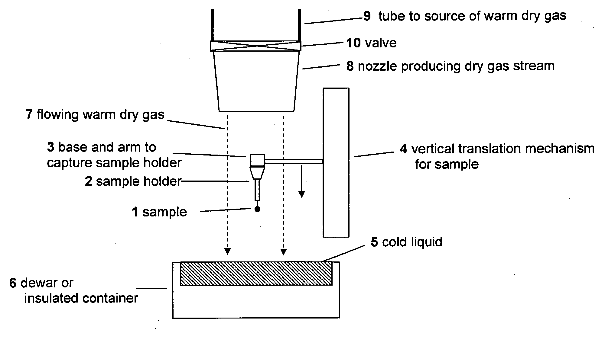
[0024]In a first preferred embodiment, the present invention overcomes the foregoing cooling effect by setting up a flow of warm, dry gas along or across the sample's path to the liquid or solid surface, thereby substantially reducing the thickness of the cold gas layer near the liquid or solid surface. Using modest N2 gas flow speeds of a few meters per second or less, experiments have established that using this technique reduces the thickness of the gas layer as defined above from 1 cm to <0.01 cm. By substantially removing the cold gas layer in this manner, measured cooling times for an 80 micron thermocouple plunged in liquid nitrogen (T=77 K) at a modest speed of 0.5 m / s drop from ˜0.2 s to ˜0.01 s, and cooling rates increase to 15,000 K / s. Reducing the sample volume to 10 micrometers (the size of single cells and the smallest protein crystals now used in protein crystallography) will decrease the cooling time to ˜0.001 s. Consequently, cooling rates of order 100,000 K / s can be achieved by plunging through gas at atmospheric pressure, at very modest speeds, and into the least expensive and least dangerous liquid cryogen.
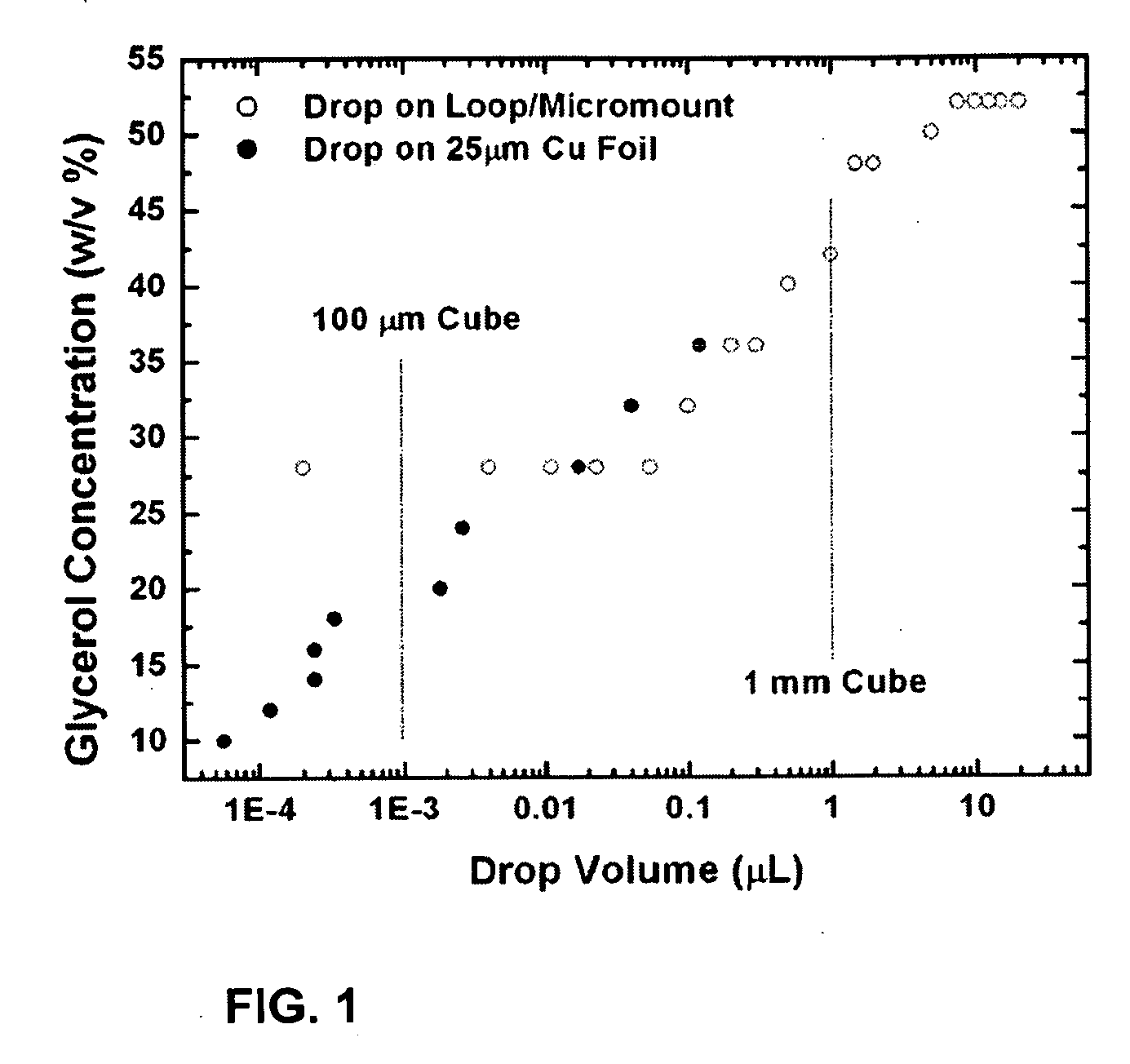
[0025]Experiments also establish that by removing the cold gas layer in this way, the minimum glycerol concentration required to achieve a vitrified sample during plunge cooling in liquid nitrogen decreases continuously with volume, to roughly 6% at a volume of 10−4 microliters, compared with roughly 30% in current practice. Extrapolation of the data to smaller volumes yields the same volume at zero glycerol concentration as has been obtained by evaporative cooling of water drops in vacuum and by spraying drops through vacuum onto a cold metal surface. Consequently, the improvements that cold gas layer removal provides are enormous, and approach the maximum cooling rates possible.
[0027]The gas stream may be coaxial with the plunge path or it may come at any angle to the plunge path, including along the cold surface. The gas nozzle or outlet may be held in a fixed position, or it may be attached to the vertical translation mechanism that holds the sample so that it moves with the sample. The size and shape of the nozzle, its distance above the surface of the liquid cryogen, and the gas flow velocity exiting it can be adjusted to produce the most efficient removal of the cold gas layer and the largest temperature gradient near surface of the liquid cryogen or solid surface.
[0028]The gas stream may be continuous, or it may be pulsed on using, e.g., a mechanically, pneumatically or electrically actuated valve just before the plunge and then turned off after the plunge. Pulsing the gas stream can minimize evaporation of liquid cryogen and, in the case of liquid cryogens held at temperatures well below their boiling temperatures (e.g., propane or ethane) or solids surfaces, minimize warming of the liquid or solid near the surface.
[0032]In addition to the foregoing mechanisms, a thin shield can be placed immediately above the liquid cryogen or solid surface, and cover most or all of it. If it is of an insulating material and has integral radiation shielding (e.g., an aluminized mylar film), it can be used to reduce condensation and freezing of water vapor onto the cold surface between plunges. It can also reduce the exposed area and heat transfer, reducing evaporation of liquid cryogens. Reducing the exposed area may also reduce the native height of the cold gas layer, and also the flow speed and flow volume of the warm dry gas needed to remove it. A small shutter or aperture in the shield can be opened when the sample is plunged.

Problems solved by technology

However, the freeze-thaw cycle often causes changes in protein structure that affect protein function, as well as protein aggregation and precipitation.
Current methods typically involve an initial slow cooling over dry ice (Tv=195 K) followed by more rapid cooling in liquid nitrogen to T=77 K. Sperm survival rates and especially fertilization rates after cryopreservation and thawing are highly variable and often extremely poor.
Protein and virus crystals are easily damaged by the X-rays used to measure their structures.
Diffusion of hydroxyl radicals, hydrogen radicals and other reactive species created by X-ray absorption is then limited, reducing their ability to attack the protein.
These methods damage the crystals, reducing the accuracy and detail of the molecular structure that can be obtained from X-ray diffraction measurements on them.
For liquid samples, the gas evolution problem can be eliminated by freezing on a cold metal surface, but cooling on metal surfaces is less effective and / or damaging for protein crystals, cells and tissues.
The growth of ice crystals as the water freezes may puncture cell walls, rupture protein crystal lattices, and cause other damage to biological samples.
However, cryorprotective agents, especially at large concentrations, can cause osmotic shock to the sample leading to cell rupture or crystal cracking, changes in protein conformation, and other chemical and physical changes that degrade the sample before cooling and / or during subsequent warming.
Changes in these properties that occur during the time the sample is cooling can lead to precipitation of salt or protein, conformational heterogeneity of proteins, changes in membrane structure, and other problems so that the structure of the cryopreserved sample deviates from the initial structure.
Reported cooling rates are 300-1500 K / s, so that the time for the crystal to cool from 273 K to 120 K is of order 0.1 to 1 s. Even when substantial concentrations of cryoprotectants (e.g., 30% glycerol) are used, these modest cooling rates result in substantial crystal damage as evident from X-ray diffraction measurements.
This damage is a major factor limiting the quality of the resulting molecular structure.
They cannot survive such high speed impacts with liquid cryogens, and the splashing when they (and their sample holders) impact the liquid cryogen is problematic.
The need for sending samples through vacuum (or low pressures) complicates cooling apparatus and protocols, and the evaporation and resulting dehydration of samples required for evaporative cooling may not accurately preserve the native sample structure.
Consequently, exposure of larger samples to vacuum or reduced pressures prior to or during a plunge into a cold liquid can cause slower cooling and more cooling related damage than when samples move through gas at atmospheric pressure (whose high thermal conductance and thermal mass minimizes sample cooling even the presence of evaporation.)

Method used


Image

  • System and method for increased cooling rates in rapid cooling of small biological samples
  • System and method for increased cooling rates in rapid cooling of small biological samples
  • System and method for increased cooling rates in rapid cooling of small biological samples

Examples


Embodiment Construction

[0046]Before a more detailed consideration of the various preferred embodiments of the present invention will be presented, the exponent and investigations conducted by the inventors which ultimately led to the creation of the present invention will be discussed.

[0047]First, the inventors have investigated flash cooling by immersion in liquid nitrogen and liquid propane of common water-cryoprotectant mixtures as a function of the volume cooled. The liquid drop samples were cooled by plunging them from air into a Dewar flask of liquid nitrogen or propane, the same method that is used for flash cooling protein crystals for cryocrystallography. FIG. 1 shows the minimum glycerol concentration required to obtain a vitrified sample upon plunging into liquid nitrogen. Open circles are data collected by plunging drops held in tungsten wire loops (for volumes above 1 μl) or in microfabricated polyimide loops (below 1 μl) into liquid nitrogen at Tv=77 K without removing the cold gas layer. So...


PUM


Abstract

A method and devices for rapid cooling of small biological samples by plunging them in a cryogenic liquid, such as liquid nitrogen, or contacting them with a cryogenic metal surface, reduce or eliminate the cold gas layer that forms above the liquid cryogens or cryogenic surfaces, producing an abrupt transition from ambient (e.g., room) temperature to the cryogen temperature as the sample enters the liquid or contacts the surface. To reduce or eliminate the effects of the cold gas layer, a flow of warm dry gas can be directed along the plunge path, for example. By removing this cold gas layer, cooling times for a 10 micron sample (the size of single cells and the smallest protein crystals now used protein crystallography) will decrease to ˜0.001 s.

Description

CROSS REFERENCE TO RELATED APPLICATIONS[0001]This application is a continuation under 35 U.S.C. 120 and 365(c) of International Application No. PCT / US07 / 07963, which was filed on Mar. 30, 2007, designates the U.S. and claims the benefit under 35 U.S.C. 119(e) of U.S. Application Nos. 60 / 787,206, filed Mar. 30, 2006, and 60 / 60 / 847,666, filed Sep. 28, 2006, which are hereby incorporated by reference.BACKGROUND OF THE INVENTION[0002]1. Field of the Invention[0003]The present invention relates in general to a method and devices for rapid cooling of small (10 microliter or smaller) biological samples to cryogenic temperatures (approximately 150 K or less). The method and devices minimize the thickness of the cold gas layer that forms above the surfaces of liquids and solids (e.g., copper) cooled to cryogenic temperatures, replacing this cold gas layer with gas at another, warmer and more uniform temperature at the same or similar pressure.[0004]2. Description of the Background Art[0005]C...

Claims


Application Information

Patent Timeline
IPC IPC(8): F25D25/00F25B19/00
CPCA01N1/02A01N1/0242G01N1/42A01N1/0268A01N1/0257
Inventor THORNE, ROBERT E.WARKENTIN, MATTHEW W.BEREJNOV, VIATCHESLAV
Owner CORNELL RES FOUNDATION INC
Learn More