
Non-aqueous electrolyte battery and method of manufacturing the same

a non-aqueous electrolyte, battery technology, applied in the direction of cell components, final product manufacturing, sustainable manufacturing/processing, etc., can solve the problems of battery with an elevated end-of-charge voltage losing the stability of the crystal structure, deterioration of cycle performance and storage characteristics, and significant battery performance degradation, etc., to achieve the effect of increasing the internal resistance of the battery and reducing the energy density of the battery

Inactive Publication Date: 2009-05-28
SANYO ELECTRIC CO LTD
View PDF18 Cites 50 Cited by
  • Summary
  • Abstract
  • Description
  • Claims
  • Application Information

AI Technical Summary

Benefits of technology

[0042]However, since the type of the filler particles has very small impact on the advantageous effects of the invention, it is also possible to use, in addition to the above-mentioned substances, filler particles made of other substances such as zirconia and magnesia, and sub-micron particles made of an organic substance, such as polyimide, polyamide, or polyethylene.
[0043]It is desirable that the filler particles have an average particle size greater than the average pore size of the separator main body.
[0044]If the filler particles have an average particle size smaller than the average pore size of the separator main body, the separator main body may be pierced in some portions when winding and pressing the electrode assembly during the fabrication of the battery, and consequently the separator main body may be damaged considerably. Moreover, the filler particles may enter the pores of the separator main body and degrade various characteristics of the battery. To avoid such problems, the average particle size of the filler particles should be controlled as described above.
[0045]It is preferable that the filler particles have an average particle size of 1 μm or less. In addition, taking the dispersion capability of the slurry into consideration, it is preferable to use inorganic particles subjected to a surface treatment with aluminum, silicon, or titanium.
[0046]It is desirable that the coating layer have a thickness of 4 μm or less, more desirably 2 μm or less.
[0047]Although the above-described advantageous effects become more significant when the thickness of the coating layer is larger, an excessively large thickness of the coating layer is problematic. If the thickness of the coating layer is too large, load characteristics may degrade because of an increase in the internal resistance of the battery, and the battery energy density may also decrease because an excessively large thickness of the coating layer means less amounts of the active materials in the positive and negative electrodes. For that reason, it is desirable that the coating layer have a thickness of 4 μm or less, particularly desirably 2 μm or less. It should be noted that the trapping effect is sufficiently obtained even when the thickness of the coating layer is small because the coating layer has a complicated, complex structure. It should be noted that when the coating layer is formed on only one side of the separator, the thickness of the coating layer means the thickness of that layer, while when the coating layer is formed on both sides of the separator, the thickness of the coating layer means the thickness of the coating layer on one side.

Problems solved by technology

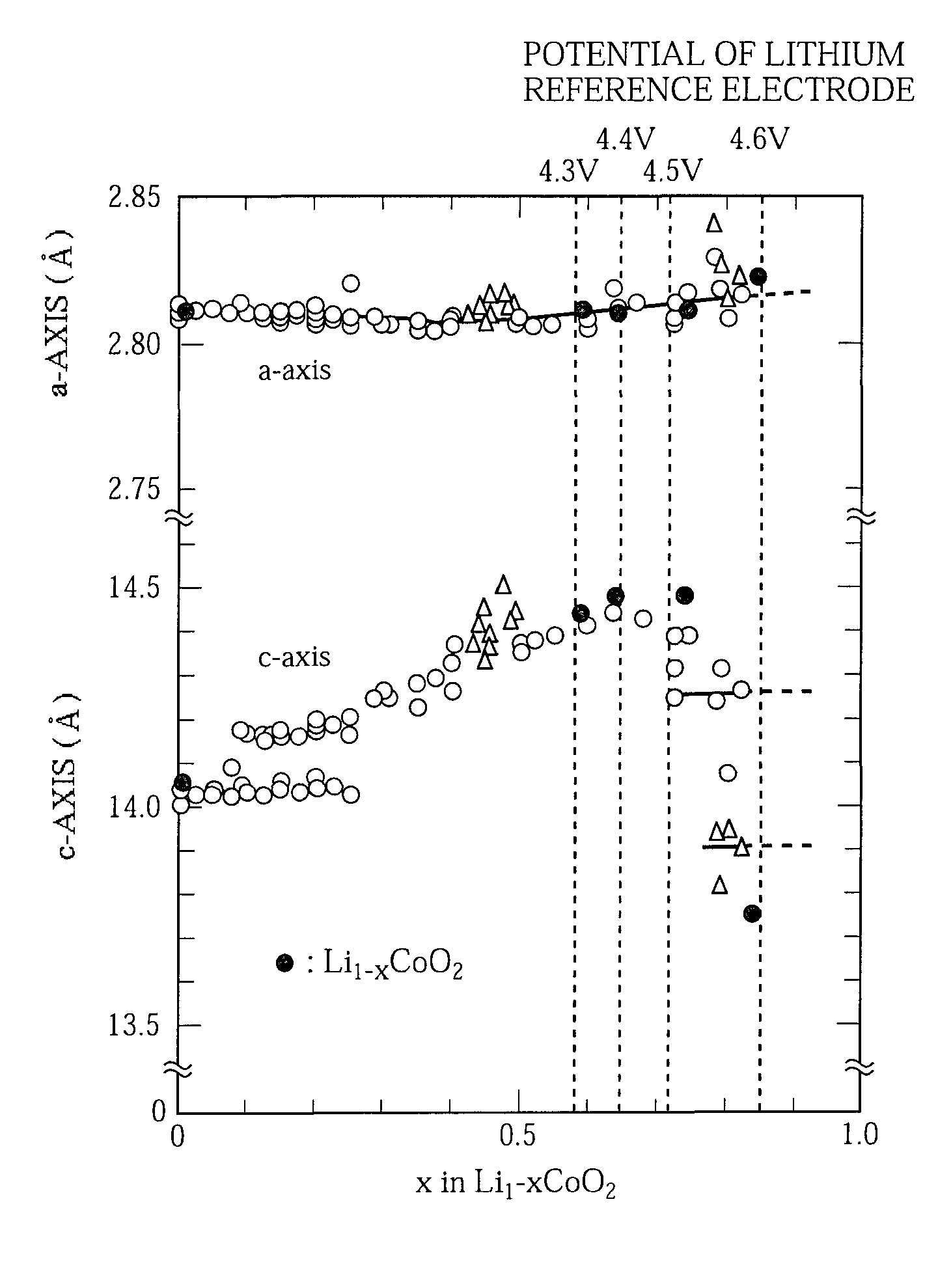
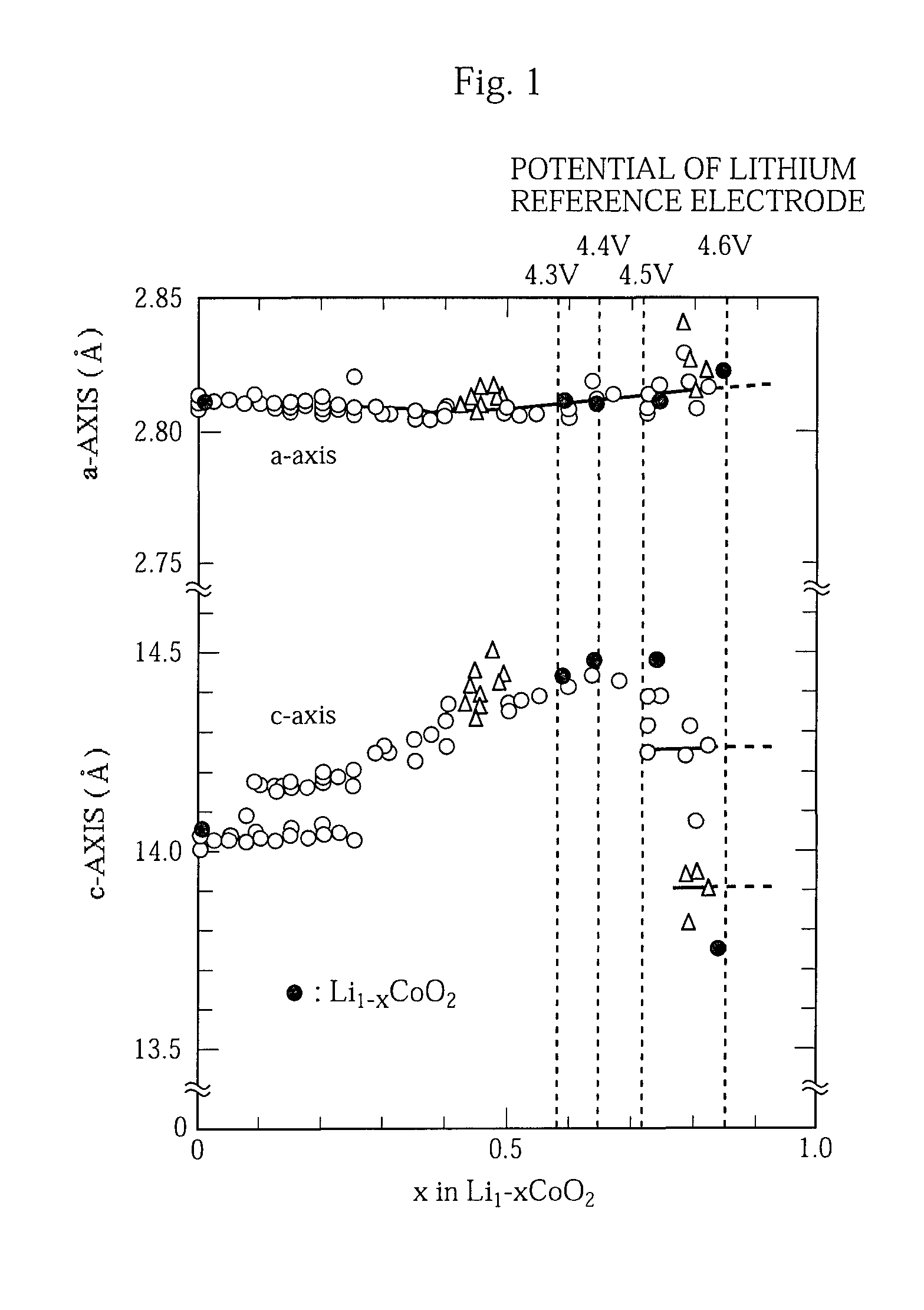
It has been found that the positive electrode of the battery with an elevated end-of-charge voltage loses the stability of the crystal structure and shows a considerable battery performance deterioration especially at high temperature.
Although the details have not yet been clear, there are indications of decomposition products of the electrolyte solution and dissolved elements from the positive electrode active material (dissolved cobalt in the case of using lithium cobalt oxide) as far as we can see from the results of an analysis, and it is believed that these are the primary causes of the deteriorations in cycle performance and storage characteristics under high temperature conditions.
In particular, in the battery system that employs a positive electrode active material composed of lithium cobalt oxide, lithium manganese oxide, lithium-nickel-cobalt-manganese composite oxide, or the like, high temperature storage causes the following problems.
This results in an increase in the battery internal resistance and the resulting capacity deterioration.
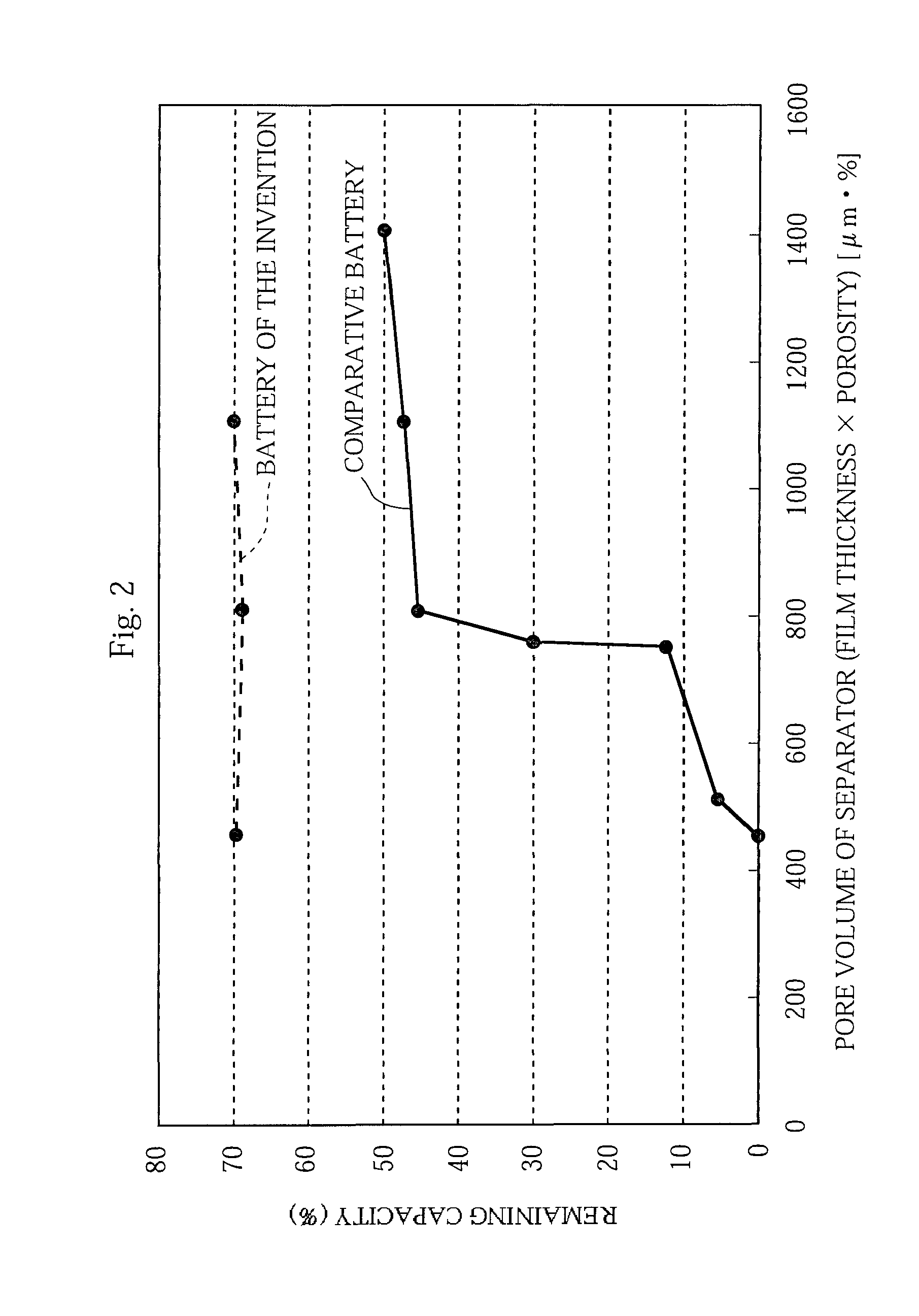
Moreover, these problems tend to worsen when a separator with a small film thickness and a low porosity is used.
However, since tetravalent cobalt is unstable, the crystal structure thereof is unstable and tends to change into a more stable structure.
It is also known that when a spinel-type lithium manganese oxide is used as the positive electrode active material as well, trivalent manganese becomes non-uniform, and dissolves away from the positive electrode as bivalent ions, causing the same problems as in the case of using lithium cobalt oxide as the positive electrode active material.

Method used


Image

  • Non-aqueous electrolyte battery and method of manufacturing the same
  • Non-aqueous electrolyte battery and method of manufacturing the same
  • Non-aqueous electrolyte battery and method of manufacturing the same

Examples


first embodiment

[0106]The first embodiment describes an embodiment in which a water-insoluble binder alone is used as the binder of the coating layer of the separator.

[Preparation of Positive Electrode]

[0107]First, lithium cobalt oxide (in which 1.0 mol. % of Al and 1.0 mol. % of Mg are contained in the form of solid solution and 0.05 mol. % of Zr is present on the surface) as a positive electrode active material, acetylene black as a carbon conductive agent, and PVDF as a binder agent were mixed together at a mass ratio of 95:2.5:2.5. Thereafter, the mixture was agitated together with NMP as a solvent, using a Combimix mixer made by Tokushu Kika Kogyo Co. Ltd., to thus prepare a positive electrode mixture slurry. Next, the resultant positive electrode mixture slurry was applied onto both sides of a positive electrode current collector made of an aluminum foil, and the resultant material was then dried and pressure-rolled, whereby a positive electrode was prepared in which positive electrode active...

second embodiment

[0112]The second embodiment describes an embodiment in which a water-insoluble binder and a water-soluble binder are used as the binder of the coating layer of the separator.

[0113]A battery was fabricated in the same manner as in described in the first embodiment above, except that the separator was prepared in the following manner and that the coating layer of the separator described below was disposed on the negative electrode side.

[0114]First, 10 mass % of TiO2 particles (rutile-type, particle size 0.38 μm, KR380 manufactured by Titan Kogyo Co., Ltd.) serving as filler particles, 1 mass % of copolymer (water-insoluble polymer) containing an acrylonitrile structures (unit) serving as a binder agent, and 1 mass % of CMC (carboxymethylcellulose sodium, water-soluble polymer) serving as a thickening agent, 1 mass % of polyalkylene-based nonionic surfactant, and 87 mass % of water as a solvent were mixed together, and a mixing and dispersing process was carried out using a Filmics mix...

third embodiment

[0115]The third embodiment describes an embodiment in which LiBF4 is added to the non-aqueous electrolyte solution.

[0116]A battery was fabricated in the same manner as in described in the first embodiment above, except that a non-aqueous electrolyte solution prepared in the following manner was used as the non-aqueous electrolyte solution and that a separator prepared in the following manner was used as the separator.

[Preparation of Non-aqueous Electrolyte]

[0117]LiPF6 and LiBF4 were dissolved at a proportion of 1.0 mole / liter (M) and at a proportion of 1 mass %, respectively, in a mixed solvent of 3:7 volume ratio of ethylene carbonate (EC) and diethyl carbonate (DEC) to prepare a non-aqueous electrolyte.

[Type of Separator]

[0118]A microporous PE film (film thickness: 12 μm, average pore size 0.1 μm, porosity 38%) was used as the separator main body, and the above-described slurry in which TiO2 was dispersed was coated only on the surface of the positive electrode side of the separat...


PUM


Abstract

[Problem] A non-aqueous electrolyte battery is provided that shows good cycle performance and good storage performance under high temperature conditions and exhibits high reliability even with a battery configuration featuring high capacity. A method of manufacturing the battery is also provided.[Means for Solving the Problem] A non-aqueous electrolyte battery is characterized in that the positive electrode active material contains at least cobalt or manganese, the separator includes a porous separator main body and a coating layer formed on at least one surface of the separator main body, and the coating layer contains filler particles and a water-insoluble binder.

Description

TECHNICAL FIELD[0001]The present invention relates to improvements in non-aqueous electrolyte batteries, such as lithium-ion batteries and polymer batteries, and methods of manufacturing the batteries. More particularly, the invention relates to, for example, a battery structure that is excellent in cycle performance and storage performance at high temperature and that exhibits high reliability even with a high-capacity battery configuration.BACKGROUND ART[0002]Mobile information terminal devices such as mobile telephones, notebook computers, and PDAs have become smaller and lighter at a rapid pace in recent years. This has led to a demand for higher capacity batteries as the drive power source for the mobile information terminal devices. With their high energy density and high capacity, lithium-ion batteries that perform charge and discharge by transferring lithium ions between the positive and negative electrodes have been widely used as the driving power sources for the mobile in...

Claims


Application Information

Patent Timeline
IPC IPC(8): H01M4/50B05D5/12H01M4/131H01M4/48H01M4/485H01M4/505H01M4/52H01M4/525H01M10/052H01M10/058H01M10/36
CPCH01M4/131H01M4/485H01M4/505Y02T10/7011H01M10/052H01M10/058Y02E60/122H01M4/525Y02E60/10Y02P70/50H01M4/62H01M50/443H01M50/449H01M50/491H01M50/42H01M50/463H01M50/446H01M50/431H01M10/42H01M10/0563H01M2010/4292Y02T10/70
Inventor MINAMI, HIROSHIOGASAWARA, TAKESHIIMACHI, NAOKIKAIDUKA, ATSUSHIBABA, YASUNORIKIDA, YOSHINORIFUJITANI, SHIN
Owner SANYO ELECTRIC CO LTD
Learn More