Flexible, porous ceramic composite film

a composite film, porous technology, applied in the direction of cell components, cell component details, electrochemical generators, etc., can solve the problems of high production cost, limited structural stability of materials, undesirable limits on the thinness of separators, etc., to achieve surprising flexibility and handling strength

Active Publication Date: 2009-07-16
TDK EDISON LLC
View PDF8 Cites 28 Cited by
  • Summary
  • Abstract
  • Description
  • Claims
  • Application Information

AI Technical Summary

Benefits of technology

[0014]The present invention provides a flexible, porous ceramic composite film suitable for use in a thermal battery, in which the film comprises 50% to 95% by weight of electrically non-conductive ceramic fibers comprising a coating of magnesium oxide on the surface of the fibers in an amount in the range of 5% to 50% by weight. The ceramic fibers can comprise Al2O3, AlSiO2, BN, AlN, or a mixture of two or more of the foregoing, preferably Al2O3, AlSiO2, or a combination thereof (e.g., 50% to 95% by weight Al2O3 and 5% to 50% by weight AlSiO2). In a particularly preferred film, the ceramic fibers comprise 56% by weight Al2O3 and 19% by weight AlSiO2 and the magnesium oxide coating is present at 25% by weight. The magnesium oxide coating interconnects the ceramic fibers providing a porous network of magnesium oxide-coated fibers having a porosity of not less than 50% by volume (preferably 70 to 95%). Preferably, the ceramic fibers are up to 10 microns in diameter and 1 mm in length. In some preferred embodiments the film has a thickness of less than 12 mils (0.3 mm), e.g., 5 to 10 mils (about 0.13 to 0.26 mm). Preferably, the film includes pores up to 5 microns in average diameter. Advantageously, the porous ceramic composite (PCC) films of the present invention are manufactured without the use of a high-pressure hydraulic press, and can be prepared in precursor sheets that can be readily cut to any desired shape or size up to 250 mm diameter. The PCC films also exhibit surprising flexibility and handling strength.

Problems solved by technology

Thermal batteries are the reserve power “of choice” on board many weapon and defense systems, due to their very long shelf life (about 25 years).
Because of its unacceptable high production cost (e.g., due to difficult, high temperature fabrication), and difficulty in initiating wetting with molten halide, the use of BN as a separator has been abandoned in favor of high-surface area MgO powder-based separators.
A significant drawback of MgO separators is the limited structural stability of the material, which results in undesirable limits on thinness of the separator that can be obtained with this material.
Due its frangible nature, formation of a porous MgO structure with sufficient compressive strength for use in thermal batteries is limited to materials having only about a 50% open volume fraction available for receiving a working fluid, such as a molten halide electrolyte.
The low open volume of such materials imposes performance limitations in thermal battery applications, especially if there is structural disintegration (e.g., due to mechanical stressed during manufacture, etc.).
Thinner MgO separators are impractical due to the physical strength limitations inherent in the MgO pressed-powder materials.
Unfortunately, MgO powder wafers have limited handling strength, and generally must be at least about 1 mm in thickness for practical use in thermal batteries.
Thinner MgO tends to crack or break, thus compromising the integrity of the entire battery.
Larger diameter wafers exacerbate the handling problems.
In addition, volumetric changes of the active electrolyte material tends to distort the electrolyte / separator interface, which leads to cell shorting.
Wafer fabrication and battery assembly involve substantial hand labor, partly due to the frangible nature of MgO separators.
Production of thinner or thicker parts is notably more difficult, and commonly results in low yields, and therefore, higher costs.
Similarly, large diameter wafers are difficult to uniaxially press due to increasingly larger processing equipment required to provide the necessary mechanical loads to form the wafers—typically greater than about 10,000 pounds-per-square inch (psi).
These limitations preclude many advanced battery designs.
The metal sulfide electrode material, FeS2, is a very hard material and does not compact well on its own.
This is crucial, in that unpressed electrodes with a 20-30 volume % loading of electrolyte exhibit poor performance (e.g., low energy density and low power output).

Method used


Image

  • Flexible, porous ceramic composite film
  • Flexible, porous ceramic composite film
  • Flexible, porous ceramic composite film

Examples


example 1

Production of a PCC Film

[0053]A PCC film is prepared by using a blender to suspend 3.0 grams of ceramic fiber (composition of 75 / 25 weight % Al2O3 / AlSiO2 comprising SAFFIL® Al2O3 fibers from ICI, and FIBERFRAX® AlSiO2 from Carborundum) in 0.5 liters water. The fiber then is dispersed in 8 liters of water in a papermaking machine and dropped onto a 250 mm diameter fine polyester mesh at a 6 mg / cm2 loading to provide a 250 micron thick fiber mat layer, which is then drip dried. The mat then is infiltrated at with magnesium acetate (applied as a 0.6 g / mL aqueous solution containing 5 volume % isopropanol) and dried. The infiltration and dying is repeated at least once to provide a ceramic fiber paper. Addition of isopropanol aids in wetting the ceramic fibers and enhances the drying rate. Drying is done in flowing air at about 75-100° C. After drying about 2 hours, the resulting ceramic fiber paper can be peeled from the fine polyester mesh. The pieces of ceramic fiber paper are cut to...

example 2

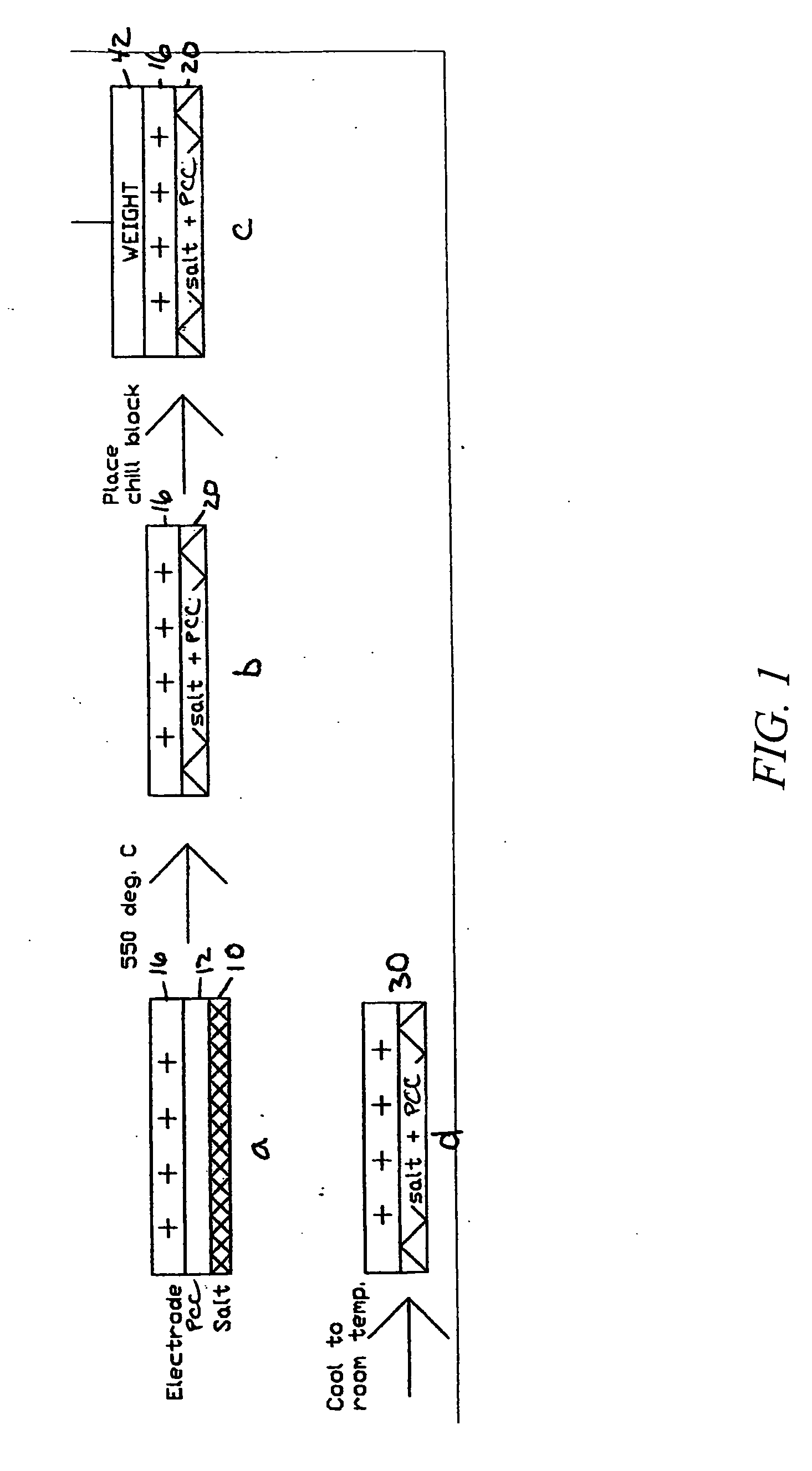
PCC Film Laminated with Pressed Electrode Pellet

[0058]A PCC film is prepared by using a blender to suspend 1.5 grams of ceramic fiber (composition of 75 / 25 weight % Al2O3 / AlSiO2 comprising ALTRA® Al2O3 fibers from Rath, Wilmington, Del., and Z-90 SAZ® P-15 AlSiO2 from K Industries, Livonia, Mich.) in 0.5 liters water. The fiber then is dispersed in 8 liters of water in a papermaking machine and dropped onto a 250 mm diameter fine polyester mesh at a 6 mg / cm2 loading to provide a 250 micron thick fiber mat layer, which is then drip dried. The mat then is infiltrated with magnesium acetate (applied as a 0.6 g / mL aqueous solution containing 5 volume % isopropanol) and dried. The infiltration and dying is repeated at least once to provide a ceramic fiber paper. Addition of 5 volume % isopropanol aids in wetting the ceramic fibers and enhances the drying rate. Drying is done in flowing air at about 75-100° C. After drying about 2 hours, the resulting ceramic fiber paper can be peeled fro...

example 3

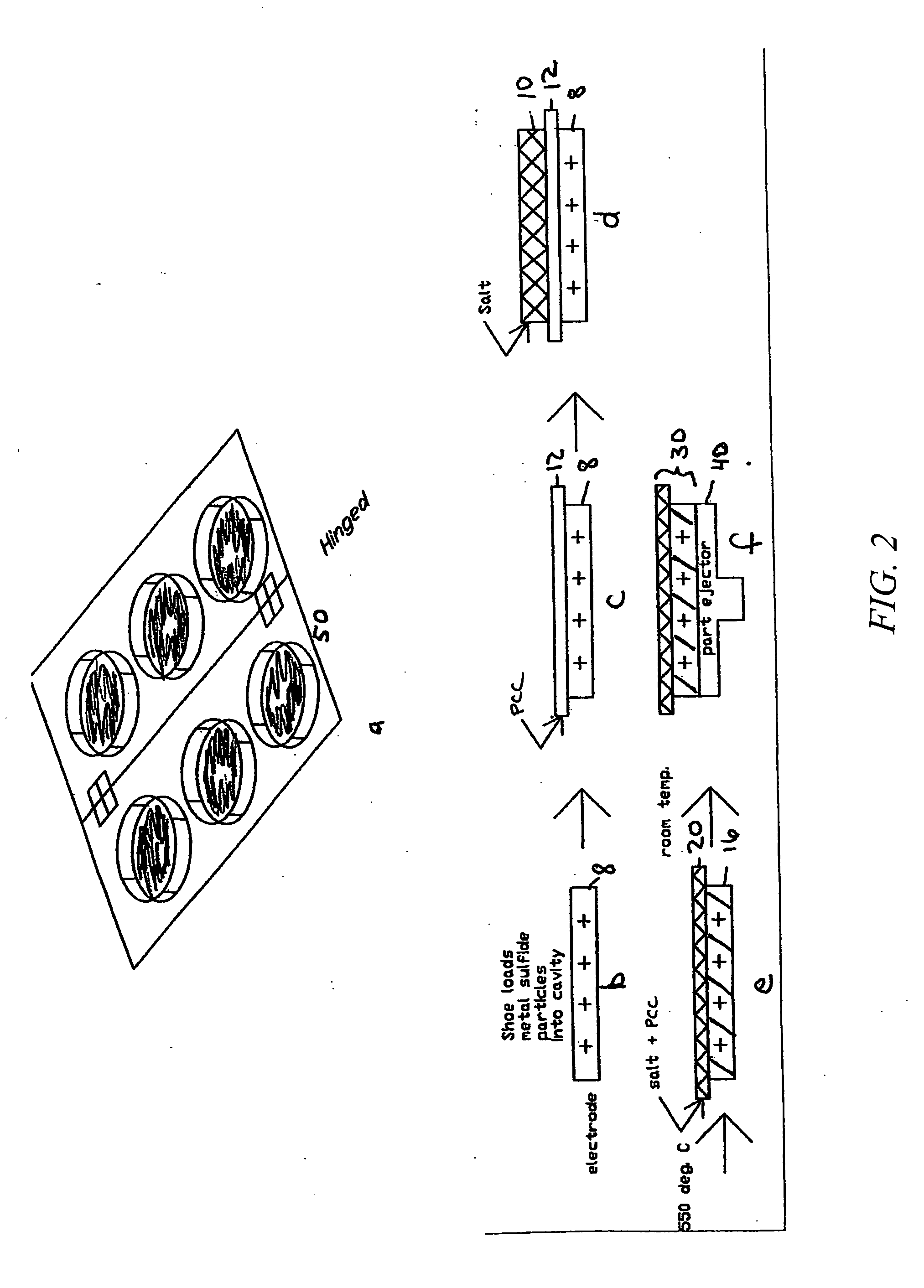
PCC Film Laminated with Electrode Particle Bed

[0061]A cut 250 micron thick PCC film as produced in Example 1 is positioned onto a cavity that has been filled with FeS2 particles, as shown in FIG. 2. The cavity is coated with BN to eliminate sticking to the cup. In this procedure, 2.3 g of the LiCl—LiBr—KBr electrolyte mixture used in Example 2 was placed onto the PCC film—this amount of electrolyte is sufficient to infiltrate both the PCC film and electrode FeS2 electrode powder. The arrangement of materials is then passed through a 550° C. tunnel furnace. After the electrolyte melts and infiltrates the two component layers, the electrolyte-to-separator weight ratio is 87:13 and the electrolyte-to-FeS2 cathode weight ratio is 25:75. The electrolyte-infiltrated PCC film becomes laminated to the FeS2 / electrolyte pellet via the infiltrated electrolyte salt.


PUM

PropertyMeasurementUnit
diameteraaaaaaaaaa
thicknessaaaaaaaaaa
thicknessaaaaaaaaaa

Abstract

A thin, flexible, porous ceramic composite (PCC) film useful as a separator for a molten-salt thermal battery comprises 50% to 95% by weight of electrically non-conductive ceramic fibers comprising a coating of magnesium oxide on the surface of the fibers in an amount in the range of 5% to 50% by weight. The ceramic fibers comprise Al2O3, AlSiO2, BN, AlN, or a mixture of two or more of the foregoing; and the magnesium oxide coating interconnects the ceramic fibers providing a porous network of magnesium oxide-coated fibers having a porosity of not less than 50% by volume. The pores of the film optionally can include a solid electrolyte salt. A laminated electrode/PCC film combination is also provided, as well as a thermal battery cell comprising the PCC film as a separator.

Description

CROSS-REFERENCE TO RELATED APPLICATIONS[0001]This application is a continuation-in-part of U.S. Ser. No. 10 / 455,087, filed on Jun. 5, 2003, which claims the benefit of provisional application Ser. No. 60 / 386,859, filed on Jun. 6, 2002, the disclosures of which are incorporated herein by reference.STATEMENT OF GOVERNMENTAL RIGHTS[0002]This invention was developed with Navy SBIR funding under Contract no. Contract N00167-99-C-0071. The U.S. government has certain rights in this invention.FIELD OF THE INVENTION[0003]The present invention relates to porous ceramic composite films useful as thin separators in thermal batteries. More particularly, this invention relates to flexible, porous ceramic composite films comprising ceramic fibers having a magnesium oxide coating, and to articles and batteries including such thin films.BACKGROUND OF THE INVENTION[0004]Thermal batteries are the reserve power “of choice” on board many weapon and defense systems, due to their very long shelf life (ab...

Claims


Application Information

Patent Timeline
Patent Type & Authority Applications(United States)
IPC IPC(8): H01M2/14C04B35/01C04B35/58B32B5/02H01M50/403H01M50/434H01M50/489H01M50/491
CPCH01M2/145C04B2235/5264H01M6/36H01M6/42H01M10/399C04B35/62847C04B35/62897C04B2235/449C04B2235/5224C04B2235/5228C04B2235/524C04B2235/5244C04B2235/5256C04B2235/526H01M2/1613Y10T428/249928Y02E60/10H01M50/44H01M50/403H01M50/491H01M50/434H01M50/489
Inventor KAUN, THOMAS D.
Owner TDK EDISON LLC
Why Eureka
Try Eureka