Conductive Filler

a technology of conductive filler and conductive layer, which is applied in the direction of soldering apparatus, manufacturing tools, and capacitors, etc., can solve the problems of rare resource, poor ductility, and insufficient melting point reduction, so as to reduce manufacturing costs and environmental load, reduce thermal damage to components, substrates and peripheral devices during mounting, and reduce the effect of environmental load

Active Publication Date: 2009-08-06
KOKI
View PDF8 Cites 16 Cited by
  • Summary
  • Abstract
  • Description
  • Claims
  • Application Information

AI Technical Summary

Benefits of technology

[0024]The conductive filler of the present invention is capable of melt-bonding at a lower temperature condition than the reflow heat treatment condition of the Sn-37Pb eutectic solder, that is, at a peak temperature of 181° C., and can be used as a bonding material in the same applications requiring heat resistance as those of the Sn-37Pb eutectic solder, that is, without melting at 160° C., and whose melting point is not substantially raised through the heat treatment during the connection. Therefore, bonding materials using the conductive filler of the present invention can reduce thermal damage to components, substrates and peripheral devices during mounting, have repairability, and further have advantages of reducing the manufacturing costs and environmental load.

Problems solved by technology

However, recently, as in the environmental regulations of the EU (RoHS directive), the problem with the hazardousness of Pb arises and making solders lead-free rapidly progresses in view of preventing contamination of the environment and human bodies.
As components reducing the melting points of lead-free solder alloys, Bi, In, Zn and the like have been confirmed to be effective, but the melting point reduction is sometimes insufficient depending on the amount ratios of them.
Bi improves wettability of a solder alloy to a substrate, but is liable to segregate on solidifying, bringing about a brittle crystal texture and a poor ductility.
It is a rare resource and a very expensive material.
Therefore, its addition at a large amount to a solder alloy results in a large cost increase (see Patent Documents 4 and 5).
Therefore, a solder alloy paste containing Zn exhibits a poor paste stability and a low corrosion resistance.
The Cu—Zn intermetallic compound layer has such problems as remarkable strength deterioration under a high temperature and high humidity environment (see Patent Document 6).

Method used


Image

  • Conductive Filler
  • Conductive Filler

Examples


examples

[0042]Hereinafter, the present invention will be described according to the Examples.

[0043]Here, the differential scanning calorimetry was conducted under a nitrogen atmosphere at a temperature rising rate of 10° C. / min in the range of 30 to 600° C. using “DSC-50”, made by Shimadzu Corporation.

(1) Manufacture of First Metal Particles

[0044]1.0 kg of Cu particles (purity: 99% by mass or more), 4.8 kg of Sn particles (purity: 99% by mass or more), 3.2 kg of Ag particles (purity: 99% by mass or more), 0.5 kg of Bi particles (purity: 99% by mass or more) and 0.5 kg of In particles (purity: 99% by mass or more) were put in a graphite crucible, and heated up to 1,400° C. and melted under an atmosphere of helium of 99% by volume or more by a high frequency induction heating apparatus. Then, the melted metal was introduced from the tip end of the crucible into an atomizing tank under a helium gas atmosphere, and thereafter atomized to fabricate first metal particles by ejecting helium gas (p...

example 3

(3) Manufactures of a Metal Particle Mixture and a Solder Paste

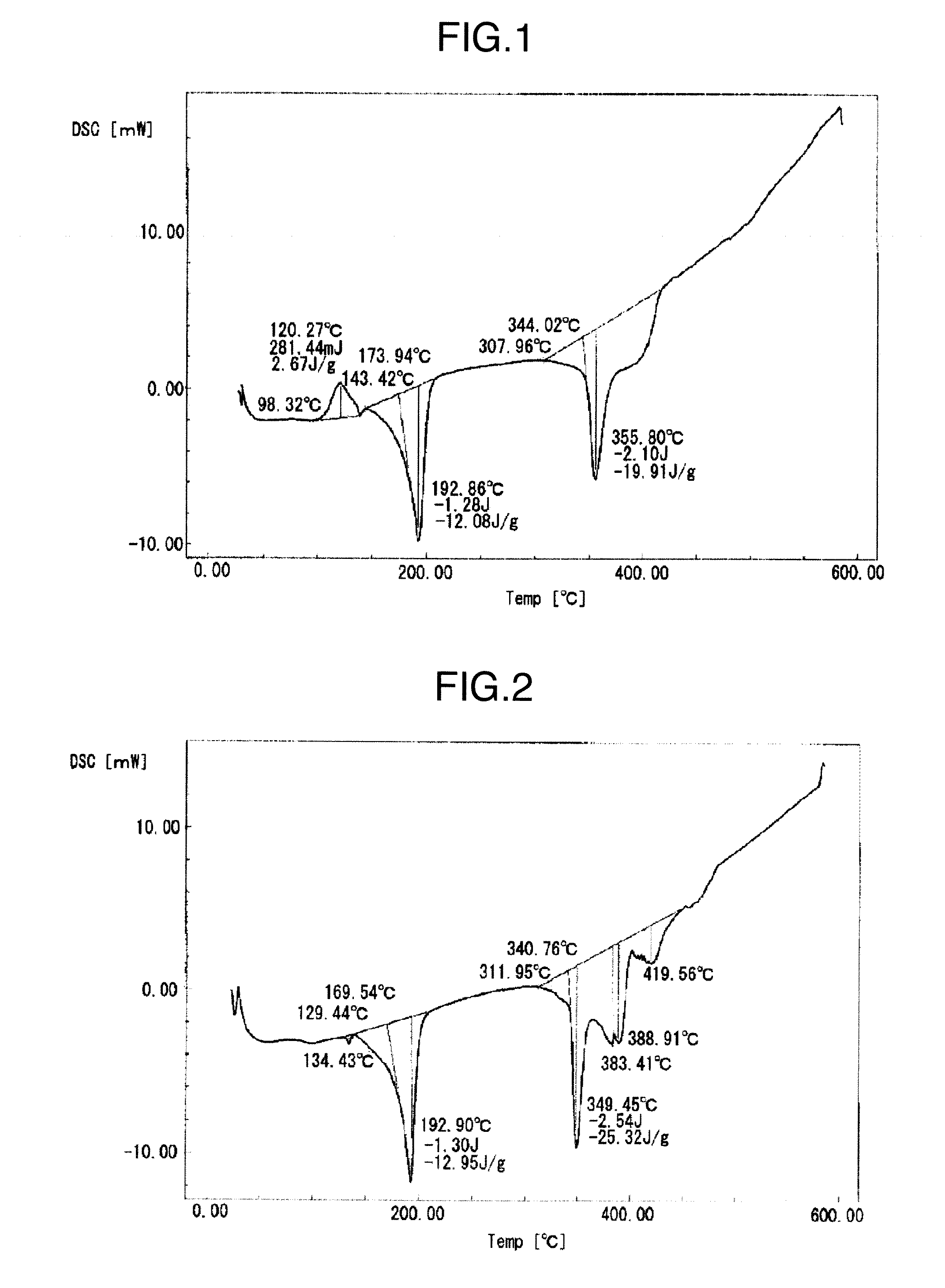
[0057]A metal particle mixture (average particle size: 4.9 μm) was fabricated by mixing the first metal particles (a) and the second metal particles (a) in the weight ratio of 100:95. The metal particle mixture was made as a conductive filler in Example 3. A DSC chart obtained by the differential scanning calorimetry of the conductive filler is shown in FIG. 1. As shown in FIG. 1, the presence of endothermic peaks at 193° C. and 356° C. is confirmed. The endothermic peak at 193° C. corresponds to a melting point of 174° C. (melt-starting temperature: solidus temperature). An exothermic peak at 120° C. is characteristically present.

[0058]Then, 90.0% by mass of the conductive filler, 6.4% by mass of a rosin flux, 1.6% by mass of triethanolamine (oxidized film removing agent), 0.4% by mass of stearic acid (active agent) and 1.6% by mass of ethylene glycol monohexyl ether (solvent) were mixed, and sequentially subjected to a...

examples 1 and 2

, and Examples 4 to 9

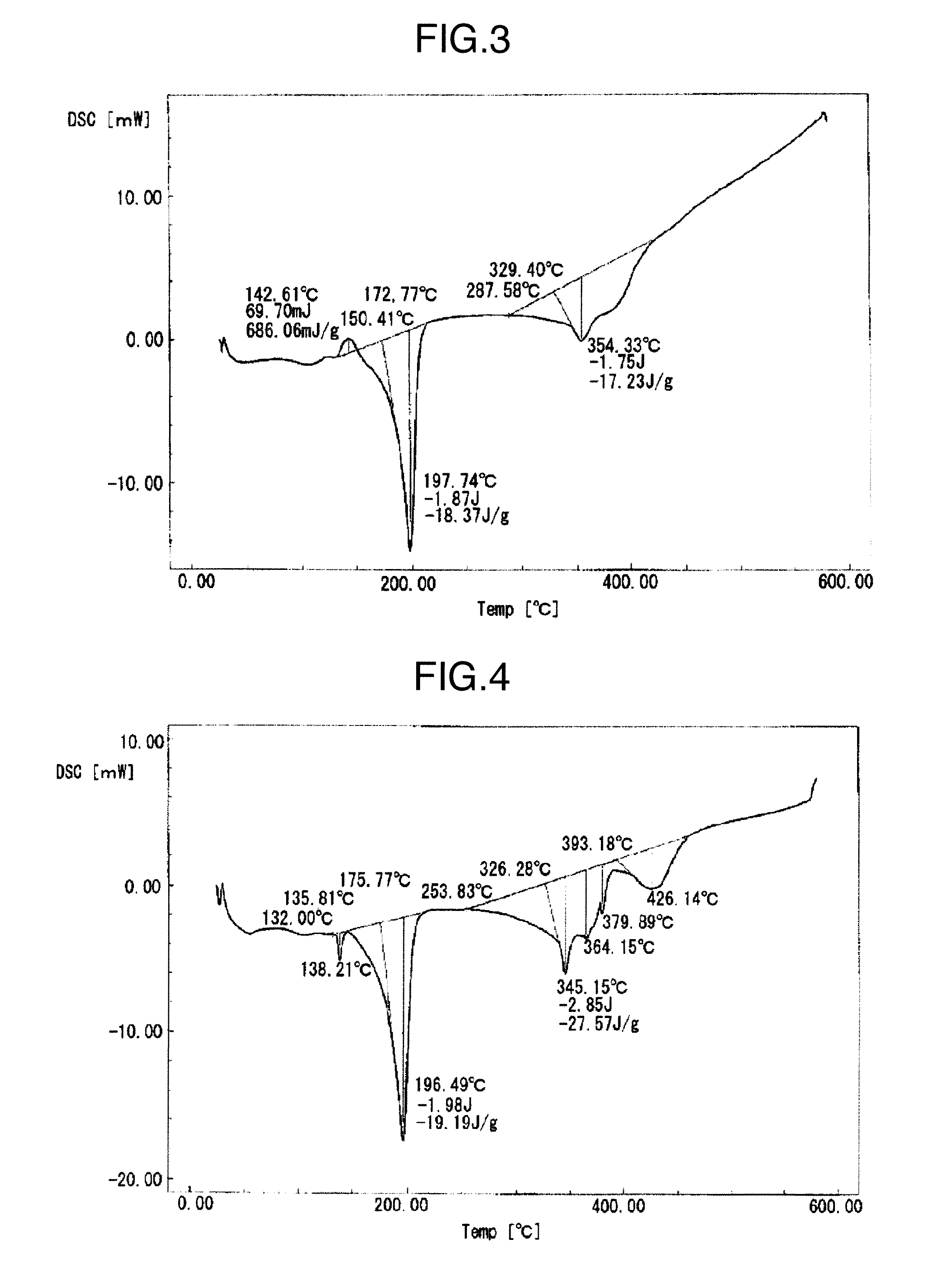
[0067]Respective metal particle mixtures in which the mixing ratios of the first metal particles (a) and the second metal particles (a) or the second metal particles (b) are changed as described in Table 1 in the conductive filler of Example 3 described above, were fabricated, and made respective conductive fillers of Examples 1 and 2 and Examples 4 to 9. The conductive fillers were made into pastes by the same method as in Example 3; the pastes were subjected to the heat treatment; thereafter, the chip bonding strengths were measured, and the results are shown in Table 1. A DSC chart obtained by the differential scanning calorimetry of the conductive filler of Example 5 is shown in FIG. 3; and a DSC chart obtained by the differential scanning calorimetry of the solder paste fabricated from the conductive filler after the peak-181° C. heat treatment is shown in FIG. 4.


PUM

PropertyMeasurementUnit
temperatureaaaaaaaaaa

Abstract

Disclosed is a conductive filler which can be fusion-bonded under lower temperature conditions (with the peak temperature of not less than 181° C.) than the reflow heat treatment conditions for an Sn-37Pb eutectic solder. This conductive filler is applicable to heat-resistant uses similar to those of the Sn-37Pb eutectic solder. The conductive filler is a mixture of first metal particles composed of an alloy having a chemical composition including 25-40% by mass of Ag, 2-8% by mass of Bi, 5-15% by mass of Cu, 2-8% by mass of In and 29-66% by mass of Sn, and second metal particles composed of an alloy having a chemical composition including 5-20% by mass of Ag, 10-20% by mass of Bi, 1-15% by mass of Cu and 50-80% by mass of Sn. In the mixture, 20-10,000 parts by mass of the second metal particles are contained per 100 parts by mass of the first metal particles.

Description

TECHNICAL FIELD[0001]The present invention relates to a conductive filler used in bonding materials for electric and electronic devices, particularly for a lead-free soldering material and a conductive adhesive.BACKGROUND ART[0002]Solders are generally used for bonding metal materials, and are supposedly alloy materials having a melting temperature range (a range from a solidus temperature to a liquidus temperature) of 450° C. or less. Conventionally, when electronic components are mounted on printed boards, an Sn-37Pb eutectic solder of 183° C. in melting point is used and the reflow heat treatment is performed mainly in the temperature range of about 200° C. to 230° C. The reflow heat treatment condition is generally set at a temperature range of 10 to 50° C. higher than the melting point of a solder alloy.[0003]However, recently, as in the environmental regulations of the EU (RoHS directive), the problem with the hazardousness of Pb arises and making solders lead-free rapidly pro...

Claims


Application Information

Patent Timeline
Patent Type & Authority Applications(United States)
IPC IPC(8): H01B1/22
CPCB23K35/262B23K35/30H05K2201/0272H05K3/3484C22C13/02H05K3/3485B23K35/3006B23K35/0244B23K35/383C22C13/00
Inventor TANAKA, NORIHITOSHIRATORI, TSUYOSHI
Owner KOKI
Why Eureka
Try Eureka